Table 11 Electrical Data
(F/G)9MXT TWO-STAGE, ECM BLOWER FURNACES
UNIT SIZE
0401410
0401712
0601412
0601714
0801716
0802120
1002120
1202422
UNIT SIZE
0401410
0401712
0601412
0601714
0801716
0802120
1002120
1202422
VOLTS-
HERTZ-
PHASE
115-60-1
115-60-1
115-60-1
115-60-1
115-60-1
115-60-1
115-60-1
115-60-1
VOLTS-
HERTZ-
PHASE
115-60-1
115-60-1
115-60-1
115-60-1
115-60-1
115-60-1
115-60-1
115-60-1
OPERATING
VOLTAGE
RANGE*
Max* Min*
127 104
127 104
127 104
127 104
127 104
127 104
127 104
127 104
MAXIMUM
UNIT
AMPS
7.5
7.5
7.6
10.7
10.1
13.1
13.5
12.0
UNIT
AMPACITY#
10.3
10.3
10.4
14.3
13.5
17.3
17.7
15.9
(F/G)9MXE SINGLE-STAGE, ECM
OPERATING
VOLTAGE
RANGE*
Min*
104
104
104
104
104
104
104
104
MAXIMUM
UNIT
AMPS
7.5
7.5
7.6
10.7
10.1
13.1
13.5
12.0
Max*
127
127
127
127
127
127
127
127
* Permissible limits of the voltage range at which the unit operates satisfactorily.
MINIMUM
WIRE
SIZE
AWG
14
14
14
14
14
12
12
12
BLOWER FURNACES
UNIT
AMPACITY#
10.3
10.3
10.4
14.3
13.5
17.3
17.7
15.9
MINIMUM
WIRE
SIZE
AWG
14
14
14
14
14
12
12
12
MAXIMUM
WIRE
LENGTH
FT (M)$
36 (11.0)
36 (11.0)
35 (10.7)
26 (7.9)
27 (8.2)
33 (10.1)
32 (9.8)
36 (11.0)
MAXIMUM
WIRE
LENGTH
FT (M)$
36 (11.0)
36 (11.0)
35 (10.7)
26 (7.9)
27 (8.2)
33 (10.1)
32 (9.8)
36 (11.0)
MAXIMUM
FUSE OR CKT
BKR
AMPS_
15
15
15
15
15
20
20
20
MAXIMUM
FUSE OR CKT
BKR
AMPS_
15
15
15
15
15
20
20
20
# Unit ampacity = 125percent of largestoperating component's full load amps plus 100 percent of allother potential operating components' (EAC, humidifier, etc.) full load
amps.
Time-delay type is recommended.
Length shown is as measured one way along wirepath between unit and service panelfor maximum2 percent voltage drop.
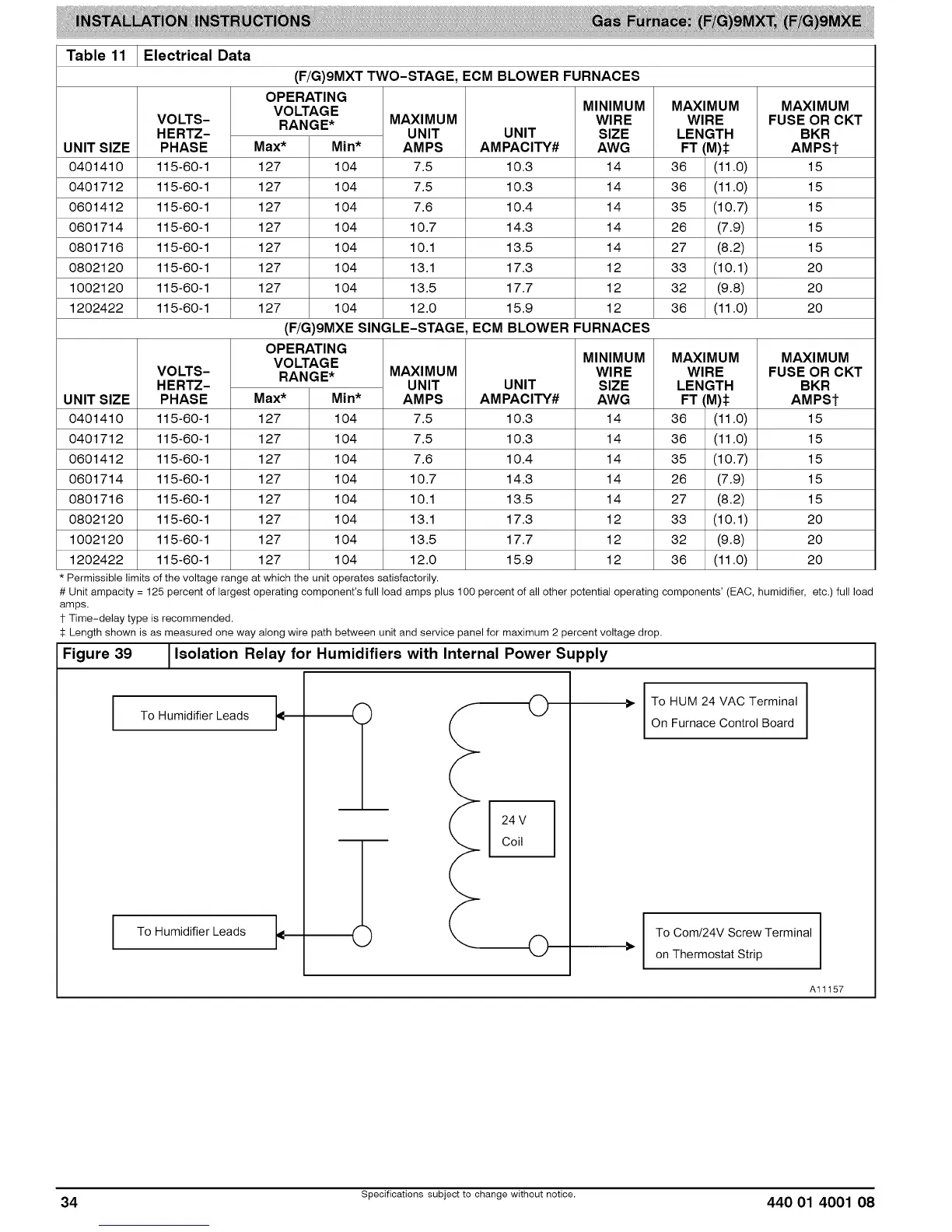
Figure 39 1Isolation Relay for Humidifiers with Internal Power Supply
To Humidifier Leads
To Humidifier Leads
O
24 V
Coil
O
I
• To HUM 24 VAC Terminal I
I
On Furnace Control Board
To Com/24V Screw Terminal
on Thermostat Strip
Al1157
34 Specifications subject to change without notice. 440 01 4001 08