Theconcentricventkitcurrentlycannotbemodifiedtoattach
anelbowtotheventportionoftheraincap.Ateeattachedto
theraincapcouldpotentiallydirectthefluegasplumetoward
theintakeairstreamandcontaminatetheincomingcombustion
airforthefurnace.
RefertoFigure45andFigure47forterminationsapprovedfor
useinAlbertaandSaskatchewan.
Figure45 TeeatTerminationOutlet
OPTIONALTERMINATION
BRACKET FOR 2-PIPE
TERMINATIONS _.
MIN.
SEPARATIONBETWEEN
BOTTOM OF COMBUSTION
AIRAND BOTTOM OF VENT.
12-IN. (305 MM)
ABOVE ANTICIPATED
SNOW LEVEL
A13078A
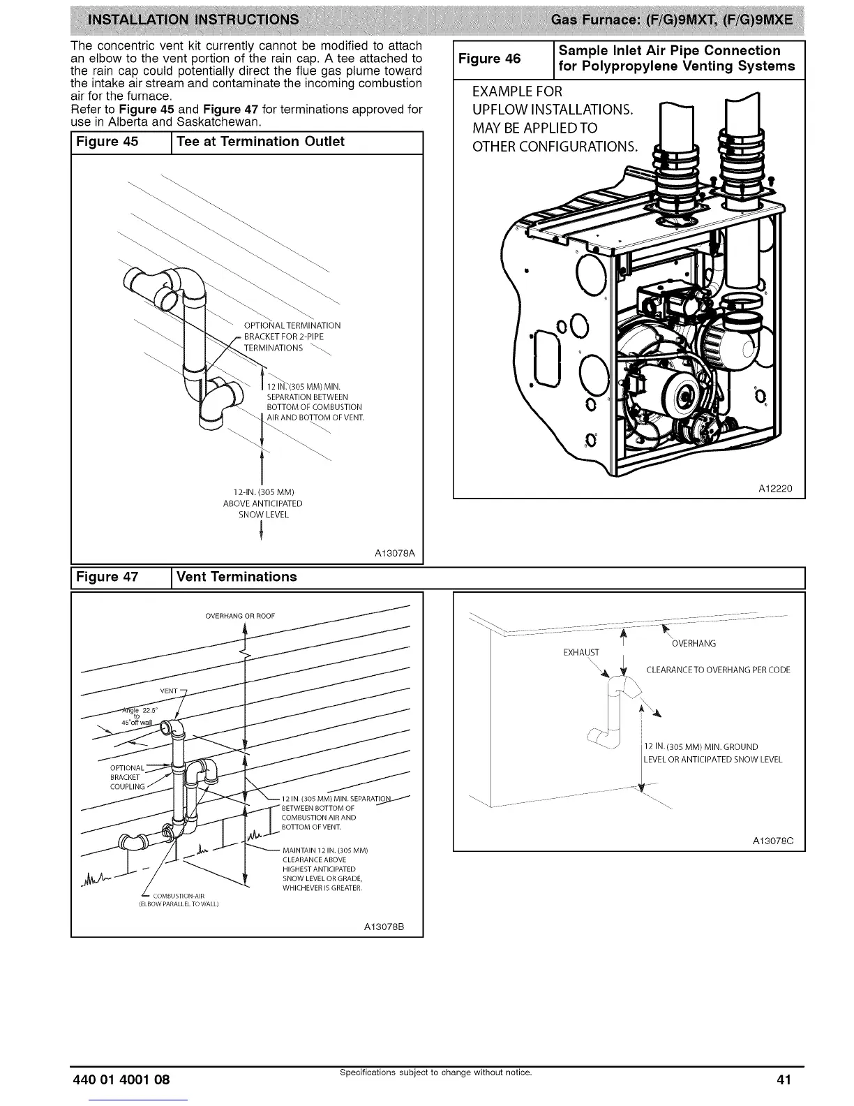
Sample Inlet Air Pipe Connection
Figure 46 for Polypropylene Venting Systems
EXAMPLE FOR
UPFLOW INSTALLATIONS.
MAY BEAPPLIED TO
OTHER CONFIGURATIONS.
A12220
Figure 47 _Vent Terminations
OPTIONAL-
BRACKET
•_ COMBUSTION AIR
(ELBOW PARALLEL TO WALL)
COMBUSTION AIR AND
BOTTOM OFVENT.
(305 MM)
CLEARANCEABOVE
HIGHEST ANTICIPATED
SNOW LEVEL OR GRADE,
WHICHEVER IS GREATER.
A13078B
OVERHANG
EXHAUST
"\_\\4_ CLEARANCE TO OVERHANG PERCODE
12 IN.(305 MM) MIN.GROUND
EVEL OR ANTICIPATED SNOW LEVEL
A13078C
440 01 4001 08 Specifications subject to change without notice. 41