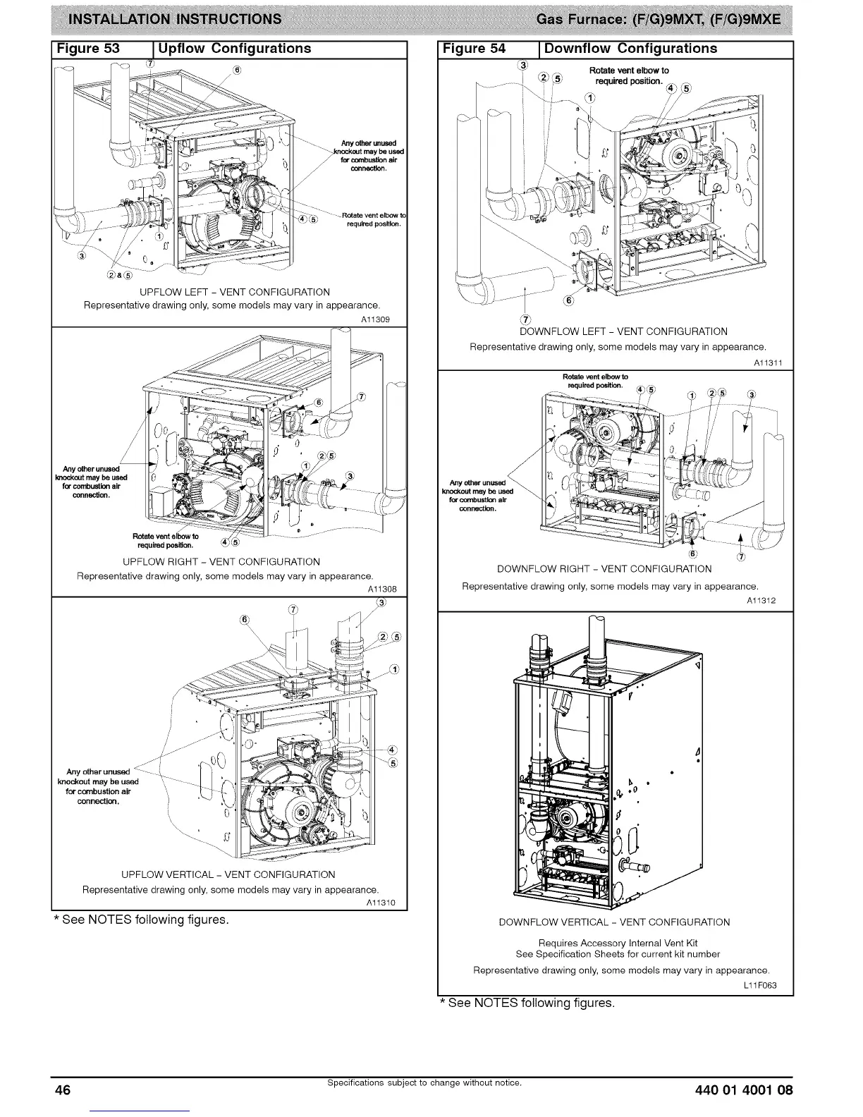
Figure 53 Upflow Configurations
. fi'_j
,< -_< _ _ F6_'
-i i __ _=
?v"_"-7_ / / _4_-_',\'_<,_ _ _-g "'
,-_V=_ "/_'-"3 + .............."........"
_2$&LSj ......
UPFLOW LEFT - VENT CONFIGURATION
Representative drawing only, some models may vary in appearaTc?,_o9_'°
f W'rF-+---_._...;.._:::::,_C-L:'%;_-'" d6_, .s_;
I "" >_' , ' ,_27c_J..._
:) t) . r ....
Rntete vent elbow to :,i_ _ ....... ......... -
requit'e_l !_ilion. _4_LS_
UPFLOW RIGHT - VENT CONFIGURATION
Representative drawing only, some models may vary in appearance.
Al1308
;€ r .z_
_._ ....
I_d<out maybeused C{ - L / 7_'
lot"combustion air ..... El J- ",,_i' _ -_, _ _y___-:',
(, o' ,_
Va
UPFLOW VERTICAL - VENT CONFIGURATION
Representative drawing only, some models may vary in appearance.
Al1310
* See NOTES following figures.
Figure 54 I Downflow Configurations
\_ Rotate ventelbowto
/
®
DOWNFLOW LEFT - VENT CONFIGURATION
Representative drawing only, some models may vary in appearance.
Alt3tt
Rotateventelbowto
required position.
@
DOWNFLOW RIGHT - VENT CONFIGURATION
Representative drawing only, some models may vary in appearance.
Alt3t2
DOWNFLOW VERTICAL - VENT CONFIGURATION
Requires Accessory Internal Vent Kit
See Specification Sheets for current kit number
Representative drawing only, some models may vary in appearance.
L11F063
* See NOTES following figures.
46 Specifications subject to change without notice. 440 01 4001 08