Do you have a question about the Tempstar N4A3 and is the answer not in the manual?
| SEER Rating | 13 |
|---|---|
| Refrigerant | R-410A |
| Energy Efficiency Ratio (EER) | 11 |
| Operating Voltage | 208/230 V |
| Operating Frequency | 60 Hz |
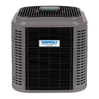
| Type | Air Conditioner |
| Compressor Type | Single Stage |
| Stages | Single Stage |
| Power Consumption (Cooling) | Varies with model |
| Air Flow (High) | Varies with model |
| Unit Dimensions (H x W x D) | Varies with model |
| Unit Weight | Varies with model |
Emphasizes reading instructions, using qualified technicians, and adhering to local electrical codes.
Stresses matching R-410A outdoor units with R-410A indoor coils and correct metering devices.
Explains the importance of proper line set sizing for efficiency and oil return, with maximum length limits.
Covers safety precautions and procedures for brazing refrigerant line connections, including valve protection.
Details the deep vacuum and triple evacuation methods for removing air and moisture from the system.
Covers line voltage connections, conduit, disconnect switches, and required supply voltage (208/230V, 60Hz).
Details permanent grounding procedures in accordance with the National Electrical Code and local codes.
Explains subcooling for TXV and superheat for piston systems, and favorable conditions for checking charge.
Details how to charge a TXV system using the subcooling method, referencing charts for pressure and temperature.
Outlines charging a piston system using the superheat method, with reference to charts for conditions.
Explains the Comfort Alert diagnostics device, its function, and LED indicators for system faults.