SHORT USER MANUAL COMMAND UNIT
2. INSTALLATION
Connections at the Command unit
Number Explanation
1
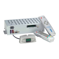
Antenna unit
2
Mounting plate
3
Elbow fitting / roof feed-through
4
Satellite harness from exterior unit (black hose)
5
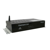
Command Unit
6
Control panel (if included in supply)
7
Coaxial cable to receiver
8
Receiver / TV with integrated receiver
9
Connect here the antenna plug (F plug) of the provided control cable to the external unit.
(Control cable and coax cable to the external unit are together in a black sheath.)
10
Fuse
11
Connect the power-supply cable provided here.
CAUTION!
Ensure that the other end of the power-supply cable is correctly connected to the onboard
electric system. If polarity is reversed, the FeatureBox may be destroyed!
Onboard system terminal 15: Ignition / D+ (optional, see 2.3) (black)
Onboard system terminal 30: Onboard system voltage 12/24V DC (red)
Onboard system terminal 31: Vehicle ground / chassis (brown)
12
Connecting cable (brown – battery negative)
13
Connecting cable (red – battery positive)
14
Body battery Coaxial cable to receiver
15
Connecting cable (black – safety circuit)
16
Ignition-switched terminal 15 of vehicle
17
optional TWIN cable
18
2. TV set only with TWIN-LNB
 Loading...