11
Assembly Instructions
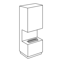
Wall Fireplace
Follow these assembly instructions to ensure safe operation.
1. The replace requires a minimum room size of 15m
2
(35m
3
).
2. Remove any protective lm onthe stove and other attachments before use.
3. The replace must be placed on a solid, straight wall.
4. The replace comes with a mounting bracket in the box. The
extinguishing lid and glass are packed with the burner.
5. Position the bracket at the desired height on the wall and mark its position
by putting a mark through the central screw hole in the bracket. Mark the
other screw holes and create the holes. Use a spirit level! Next, screw in the
other screws. (Use wall plugs and screws suited for the wall in question)
6. The screws and the bracket should be able to support a weight of up to 50kg.
7. Ensure that there is an equal amount of distance from the back of
the replace to the wall across the entire length of the replace.
8. Place the burner unit in the combustion chamber (See illustration).
Floor and freestanding models
Follow the assembly instructions to ensure safe operation.
1. The replace requires a minimum room size of 15m
2
(35m
3
).
2. The replace should be placed on a level, stable and suitable surface, so
that it cannot tip over. Keep a safe distance from light inflammable materials
when positioning the decorative replace. The minimum distance to loose
textiles, such as curtains, should be 1 meter. For stand-alone replaces
there should be 1.5 meters free space above the burner opening.
3. For the Tenderflame Indie Freestanding model: The replace should stand
on a flat surface against a wall. Optional: To secure the replace, screw the
replace to the wall. The key holes for the screws are located at the top of
each side at the back of the replace. (see: illustration). Use screws and
plugs suited for concrete, wood or plaster. The screw attachment must
support a weight of up to 50kg. It has four adjustable feet underneath.
4. Place the burner unit in the combustion chamber (See illustration).
 Loading...