● During measurement, Diodes with a good silicon
display will read the approximate resistance value.
Ω. The
if the measured resistance is greater than 10
When measuring continuity, the buzzer will sound
●
● Do not use over a 10A current measurement.
accurate resistance readings.
measured resistance value of your test to come up with
reading obtained. Subtract this value from the actual
–circuit the test leads before testing and record the
● The test leads and the internal meter wiring will
readings, choose shorter test leads for this type of
capacitors when measuring resistance.
● To maintain measurement accuracy, disconnect
The meter will measure up to a 20A current, but any
danger of sparking.
circuit, disconnect
● Before connecting the Meter in line with a return
This loading effect can cause measurement
errors in high impedance circuits.
10MΩ.
be obtained).
voltages higher than 1000 V (although reading may
warning signal will be displayed.
this is not done correctly, an alarm will sound and a
●
rotary switch to select the measurement function. If
1. Select the correct terminal input and turn the
hFE
Warning:
Range Alarm Alert On False Terminal Input
V Hz Ω 10A mAμA
mAμA
℃
hFE F 10A
10A mAμA
2.DC or AC Voltage Measurement
from electric shock, please do not attempt to measure
● T h e M e t e r has a n inp u t i m p e d a n c e o f
3.DC or AC Current Measurement
damages to the Meter.
4.Measuring Resistance, Diodes, Continuity or
Capacitance
● When measuring high resistance on 1MΩ or
above, it is normal to take several seconds to
obtain a stable reading. In order to obtain stable
measurement.
~
measurement when measuring low resistance. To
obtain accurate readings in low-resistance, short
~
Accuracy Specications
Operating temperature: 18
℃~
28
℃
Environmental humidity: Less than 75%RH
1. DC Voltage
Range Resolution
Maximum Voltage Input: 1000V (Except 200mV,
250V)
2. AC Voltage
Range Resolution
Maximum Voltage Input: 750Vrms
Frequency: 45Hz
~
400Hz
Display: True RMS
3. DC Current
Range Resolution
* When ≥5A, Continuous measurement less than 10
seconds at an interval more than 15 minutes.
4. AC Current
Range Resolution
Frequency: 45Hz
~
400Hz
* When ≥5A, Continuous measurement less than 10
seconds at an interval more than 15 minutes.
5. Resistance
Range Resolution
6. Capacitance
Range Resolution
*>40μF capacitance measurement as reference
purpose.
7. Frequency
Range Resolution
Input Amplitude:
(2kHz range) 50mV≤a≤30Vrms
(200kHz range)150mV≤a≤30Vrms
8. Temperature
~ ℃
℃ ℃
~ ℃
>100
~
1000
℃
thermocouple can only be used on less than 230
℃
temperature measurement.
9. Diode Test
10. Continuity Test
Range Resolution Remarks
11. Transistor hFE
Range Resolution Remarks
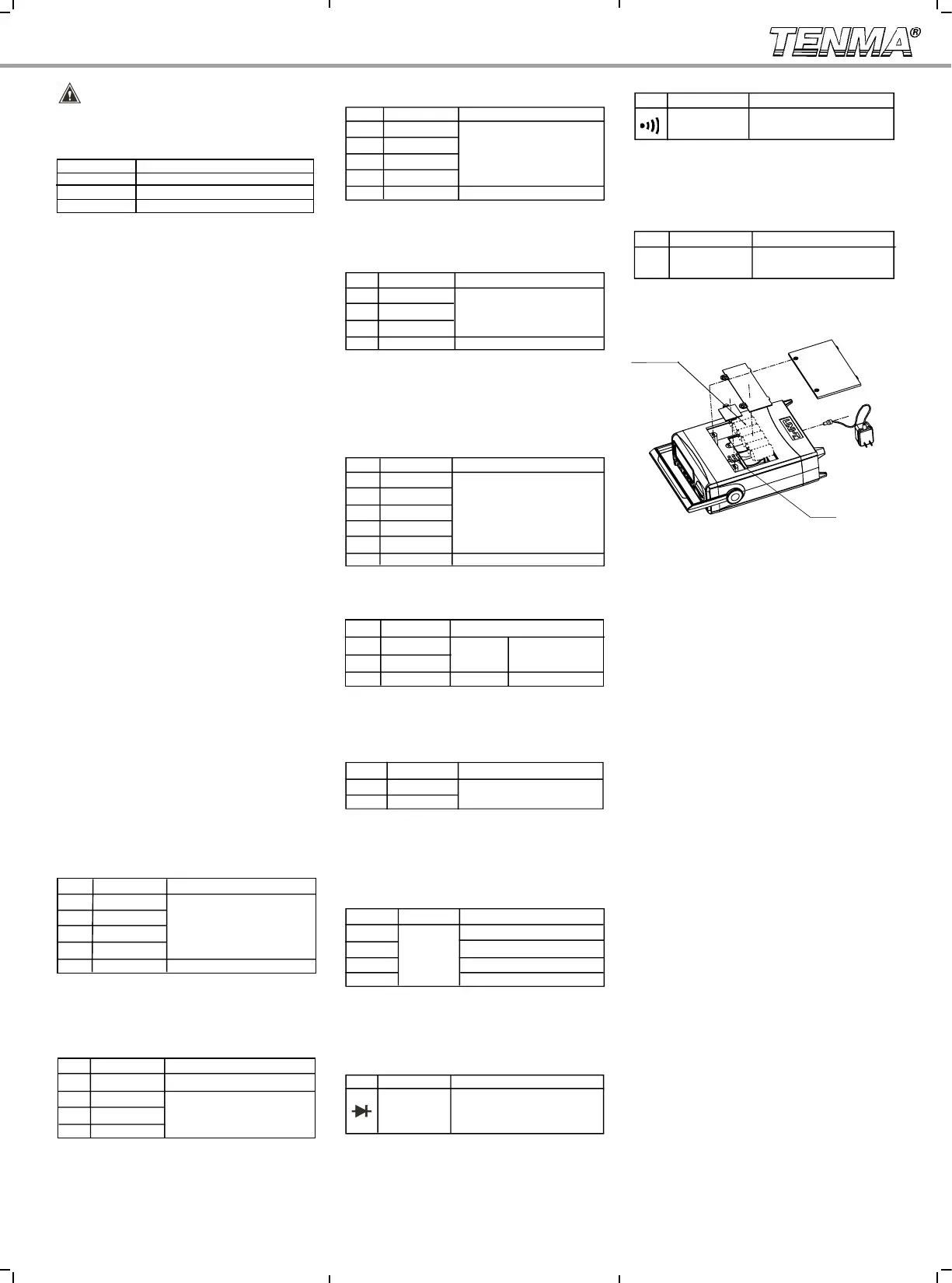
Replacing the battery(see Diagram 4)
Accuracy Tolerance:±(% Reading+Digits)
Accuracy Tolerance:±(% Reading+Digits)
Accuracy Tolerance:±(% Reading+Digits)
Accuracy Tolerance:±(% Reading+Digits)
Accuracy Tolerance:±(% Reading+Digits)
Accuracy Tolerance:±(% Reading+Digits)
Accuracy Tolerance:±(% Reading+Digits)
0.5
~
0.8V as the normal value.
Ib 0 i s a bo ut 10μA, Vce is
about 2.5V
Diagram 4
Fuse
Power
adapter
Specifications and other information shown on this
instruction manual are subject to change without
notice
To avoid personal injury or damage to the meter
the circuit current to avoid any
current over 10A could cause personal injury and
circuit power and discharge any high voltage
add about 0.1Ω 0.2Ω of error to resistance
junction typically drop to 500mV 800mV.
Input impedance is on average 10MΩ
Input impedance is on average 10MΩ
Accuracy Tolerance:±(% Reading+Digits)
20V
10mV
200V
100mV
±(1.0%+4)
1000V
1V
2V
1mV
±(0.8%+3)
200mV 0.1mV
2V 1mV
200V 100mV
1000V 1V ±(0.8%+3)
200μA 0.1μA
2mA 1μA
20mA 10μA
±(0.8%+2)
200mA 0.1mA
10A 10mA
±(2.0%+4)
2mA
1μA
20mA
10μA
±(1.0%+3)
200mA
0.1mA
10A
10mA
±(2.5%+5)
2MΩ
1kΩ
200kΩ
100Ω
20kΩ
10Ω
±(0.8%+3)
2kΩ
1Ω
200Ω
0.1Ω
20MΩ 10kΩ ±(1.2%+5)
±(1.5%+5)
2kHz 1Hz
200kHz 100Hz
-40 -20 -(8%+5)
±(2.5%+2)
1
℃
Range Resolution
>-20 0 ±(1.2%+4)
>0 100 ±(1.2%+3)
1mV
Range Resolution Remarks
Open circuit voltage is appx 3V,
Silicon junction drops between
When the circuit is disconnected with a resistance
value >100Ω, buzzer does not beep.
When the circuit has a good connection with a
resistance value ≤10Ω, the buzzer beeps continuously.
1β*
C Cell (R14) 1.5V x6
±(4%+3)
±(5%+5)
20nF 10pF
2μF 1nF
200μF* 100nF
1Ω*
O p e n c i r c u i t v o l t a g e i s
approximately 3V
thermocouple. The included point contact K -type
* Thermocouple: It is suitable to use K -type
20V 10mV ±(0.5%+2)
Accuracy: ±(% reading + digits), guaranteed for 1 year
Made in China for Tenma
 Loading...