Do you have a question about the Tenmars TM-195 and is the answer not in the manual?
Press button to power on and UNIT/ENTER to change unit. XYZ/MEM selects sensor axis.
Defines E, H fields, power density, field propagation, and near/far field conditions.
Details applications in broadcasting, mobile phones, wireless comms, Wi-Fi, and EMF safety.
Highlights broadband monitoring, non-directional sensor, and multiple measurement units.
Details display modes (Inst., MAX, AVG), isotropic measurement, low battery, and overload.
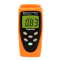
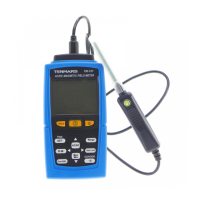
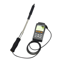
Identifies sensor, LCD, and all control buttons with their functions.
Explains all symbols and indicators on the Liquid-Crystal Display.
Covers display type, resolution, measurement method, and directional characteristics.
Details measurement ranges, resolution, sample rate, audible alarm, and units.
Lists units and describes display modes: Instantaneous, MAX, AVG, and MAX/AVG.
Covers operating temperature, humidity, dimensions, weight, and accessories.
Specifies sensor type, frequency range, and measurement conditions.
Details measurement ranges, accuracy, frequency response, and isotropy.
Specifies the overload limit for power density measurements.
Warns about invalid conversions for near-field measurements and using default units.
Explains Instantaneous, MAX, and AVG display modes with a graph.
Instructions for powering on/off and using the Data Hold function.
How to change measurement units (mV/m, V/m, µA/m, etc.).
Switching MAX/AVG modes and manually storing data (up to 200 sets).
Backlight, axis selection, and alarm ON/OFF setup procedures.
How to view saved data records and navigate through them.
How to select the display method for date and time.
Procedure for setting up the device's internal clock.
How to set the alarm limit value to monitor display values.
Procedure to clear memory and configure the analogue bar graph display.
How to set or disable the auto power off timer.
How to set the calibration factor (CAL) for result display calibration.
Application and procedure for short-term measurements in unknown field conditions.
| Frequency | 30Hz to 300Hz |
|---|---|
| Battery | 9V battery |
| Display | LCD display |
| Resolution | 0.1μT |
| Operating Temperature | 0°C to 40 °C |