Do you have a question about the Tense DT-96Y and is the answer not in the manual?
Specifies the physical dimensions and panel cutout sizes for different models.
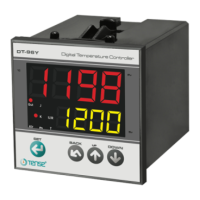
Details the 4-digit display and selectable sensor types like T/C and Pt100.
Defines the selectable measuring ranges and display resolution.
Outlines control forms, output types (Relay/SSR), and alarm output specifications.
Details Heat Hysteresis, Alarm Hysteresis, Integral Time, and Derivative Time.
Specifies the control period duration and offset adjustment for calibration.
Covers heating/cooling selection, cold junction, and line compensation.
Describes behavior during sensor failure and line compensation for Pt100.
Details the required supply voltage range and power consumption.
Covers humidity, altitude, EMC standards, safety ratings, and protection class.
Specifies operating temperature range, storage conditions, and device weight.
Highlights critical safety warnings for installation, operation, and disposal.
Provides instructions for proper mounting, wiring, and environmental considerations.
Advises on operational limits, environmental conditions, and cable management.
Describes the device as a PID controller with auto-tuning and alarm outputs.
Details selectable sensor types, control modes (P, PI, PD, PID, ON-OFF).
Covers ramp mode, anti-windup, set limits, and alarm modes.
Includes display of values, cold-junction, and line compensation.
Lists features like input offset, password protection, and optional SSR output.
Guides on entering programming mode and selecting parameter groups.
Details setting sensor types, heating/cooling functions, and hysteresis.
Covers alarm types, proportional band, integral/derivative times, and control period.
Explains setting upper/lower limits, offset, and overshoot reduction.
Lists common error messages like sensor failure and hardware issues.
Details setting the Heat Set (process SET) and Absolute Alarm Set values.
Illustrates alarm output logic for different AL.tY settings (Abs, rel, bnd, bn.i).
Explains the ON-OFF control behavior based on Hysteresis settings.
Defines PID parameters like Proportional Band (PbC), Integral Time (Ti), and Derivative Time (Td).
Provides guidance on safely cleaning the device using dry cloths.
| Mounting | Panel mount |
|---|---|
| Input | Thermocouple (K, J, R, S, E, N, T), RTD (Pt100, Cu50), 4-20mA |
| Output | Relay, SSR |
| Control Mode | PID, On/Off |
| Display | LED |
| Power Supply | 100-240V AC, 50/60Hz |
| Temperature Range | Depending on the sensor type |
| Resolution | 0.1°C or 1°C |