Do you have a question about the Tense ERD-72M and is the answer not in the manual?
Dimensions of the panel cutout required for installation.
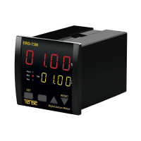
Details about the 2x4 Digit 7 Segment LED display.
Describes START/RESET/GATE inputs and their voltage compatibility.
Details on the two relay outputs (NO-0-NC, 250VAC, 2A).
Selectable time bases (hours, minutes, seconds) and number of modes.
Supply voltage, power consumption, operating temperature, and altitude.
Procedure for setting timer values like t.SEt, t.on, and t.oFF.
How to perform a reset using the front panel button.
Steps to select the time base (seconds, minutes, hours).
Guide to selecting the operational mode (0-7).
Setting the behavior for power-on reset (Yes/No).
Describes pulsed delay operation and reset behavior.
Explains periodic flashing operation with START/RESET inputs.
Details one-shot output behavior after ON and OFF triggers.
Describes delayed OFF output operation.
Explains operation where outputs follow START input and ON delay.
Details one-shot output triggered after an OFF signal.
Chronometer function that counts up with START input.
Chronometer counting with START and resetting via RESET input.
The ERD-72M Digital Timer is a versatile device designed for precise timing control in various industrial and automation applications. It features a 2x4 7-segment LED display for clear visual feedback and offers a range of operational modes to suit different timing requirements.
At its core, the ERD-72M functions as a digital timer with two independent outputs, OUT1 and OUT2, which can be configured to operate based on various timing sequences. It incorporates START, RESET, and GATE inputs, providing flexible control over the timing process. The device is capable of counting down, making it suitable for applications requiring a set duration to elapse before an action is triggered.
The timer supports eight distinct operational modes, allowing users to select the most appropriate behavior for their specific needs. These modes include:
Pulsed Delay, OFF with RESET (Mode 0): In this mode, OUT1 and OUT2 become active (ON) for a set duration ("t.SEt") after the START input is triggered. Once the START input is activated, it cannot re-trigger the timer until a RESET input is applied. Both outputs turn OFF when the RESET input is active. This mode is ideal for applications requiring a single, timed pulse that can be reset for subsequent operations.
Flashing with START/RESET (Mode 1): This mode enables periodic flashing of OUT1 and OUT2. After the START input is triggered, the outputs cycle between ON for a duration "t.On" and OFF for a duration "t.OFF." This flashing continues as long as the START input is active. Both outputs turn OFF when the RESET input is active. This mode is useful for signaling or repetitive actions. For this mode, "t.On" and "t.OFF" can be set with high precision, down to 0.1 seconds, 0.01 minutes, or 0.01 hours.
One Shot after ON and OFF (Mode 2): In this mode, OUT1 and OUT2 become active for a set duration ("t.SEt") when the START input transitions from OFF to ON, or from ON to OFF. This means a timed pulse is generated on both rising and falling edges of the START input. The START input can re-trigger the timer even if the outputs are currently active. Both outputs turn OFF when the RESET input is active. This mode is suitable for applications requiring a brief action upon any change in the START signal.
OFF Delay (Mode 3): This mode causes OUT1 and OUT2 to become active when the START input is ON. When the START input transitions from ON to OFF, the outputs remain active for a set duration ("t.SEt") before turning OFF. Both outputs turn OFF immediately if the RESET input is active. This mode is useful for maintaining an action for a short period after a triggering signal has ceased.
Follow & ON Delay (Mode 4): In this mode, OUT1 becomes active immediately when the START input is ON. OUT2, however, becomes active after a set delay ("t.SEt") once the START input is ON. Both OUT1 and OUT2 turn OFF when the START input is OFF or when the RESET input is active. This mode is suitable for sequential operations where one action starts immediately and another after a delay.
Delayed One Shot after OFF (Mode 5): This mode generates a timed pulse on OUT1 and OUT2. After the START input transitions from ON to OFF, the outputs become active for a duration "tA" and then turn OFF for a duration "tB." The START input cannot re-trigger the timer until the "tB" duration has elapsed. Both outputs turn OFF when the RESET input is active. This mode is useful for applications requiring a delayed, short action after a primary signal ends.
Chronometer - Count with START (Mode 6): In this mode, the timer counts up as long as the START input is ON. The timer freezes its count when the START input is OFF. OUT2 becomes active when the timer's accumulated count reaches the set duration ("t.SEt"). The timer resets and both OUT1 and OUT2 turn OFF when the START input is OFF after the timer reaches "t.SEt." This mode is suitable for measuring elapsed time and triggering an event upon reaching a threshold.
Chronometer - Count with START, Reset with RESET (Mode 7): Similar to Mode 6, the timer counts up when the START input is ON and freezes when it's OFF. OUT2 becomes active when the timer's accumulated count reaches "t.SEt." However, in this mode, the timer resets and both OUT1 and OUT2 turn OFF only when the RESET input is active, regardless of the START input state after "t.SEt" is reached. This mode provides more explicit control over resetting the chronometer function.
The GATE input serves to inhibit or freeze the counting process across all modes when it is active, providing an additional layer of control over the timer's operation.
The ERD-72M is designed for ease of use and robust performance. Its 72x72mm front panel allows for straightforward integration into control panels. The device accepts 24VDC inputs, making it compatible with common PNP proximity switch outputs, simplifying sensor integration.
Programming the timer's SET value and selecting time base and modes is done through a user-friendly interface involving button presses and display navigation. The "t.SEt" parameter defines the primary timing duration, while "t.on" and "t.oFF" are specific to the flashing mode. The time base can be configured for seconds, minutes, or hours, offering flexibility in setting the desired timing resolution.
A crucial usage feature is the power-on reset setting ("P.rES"). Users can choose whether the timer's SET value is reset upon power-on or if the device loads the timer value and output status from its state at the latest power failure. This memory retention capability, facilitated by EEPROM, ensures that settings are preserved even after power interruptions, enhancing reliability in critical applications.
For maintenance and protection, the manual provides important guidelines. It emphasizes the use of twisted pair and shielded signal cables to minimize electrical noise interference, recommending that the shield be connected to ground at the device side. This helps maintain signal integrity in electrically noisy environments.
The device is designed to operate within a wide temperature range, from -20 °C to 55 °C, and at altitudes up to 2000m, making it suitable for diverse environmental conditions.
While the ERD-72M is built for durability, certain maintenance considerations are highlighted to ensure its longevity and reliable operation.
The manual advises taking precautions against environmental conditions such as humidity, vibration, pollution, and extreme temperatures during installation. Proper installation practices contribute significantly to the device's lifespan and performance.
A key safety and maintenance instruction is to use a slow 250mA 250VAC fuse on the supply input of the device. This fuse acts as a protective measure against overcurrents, safeguarding the timer from potential damage due to electrical faults. It also stresses the importance of using appropriate cables for supply connections and adhering to safety regulations during installation.
For the "SS Out" (Sensor Supply Out) connections, it is recommended that the return line be directly connected to the "GND pin." Furthermore, the use of a free-wheeling diode is advised to protect the "SS Out" from inductive loads, preventing potential damage to the sensor supply output. These measures are crucial for maintaining the integrity of the sensor power supply and the overall device.
The EEPROM memory ensures that programmed settings are retained even after power loss, reducing the need for reprogramming after power interruptions. This feature contributes to reduced maintenance effort and increased operational continuity.
Overall, the ERD-72M Digital Timer is a robust and adaptable timing solution, offering a comprehensive set of functions and features for precise control in automated systems, with clear guidelines for installation and basic maintenance to ensure long-term performance.
| Frequency | 50/60 Hz |
|---|---|
| Type | Digital Timer |
| Number of Programs | 8 |
| Battery Backup | Yes |
| Display | LCD |
| Output | Relay |
| Weight | 0.2 kg |