EasyManua.ls Logo

Tense ERD-96M - User Manual

Tense ERD-96M
4 pages
Print Icon
To Next Page IconTo Next Page
Loading...
ERD-96M
DIGITAL TIMER
General Specification
1
ENG
Digital Timer with START/RESET/GATE input and OUT1 & OUT2 outputs
2x4 7 Segment LED display
Selectable 8 different modes
Counts down hour/minute/second
Loads Timer value & OUT status at the latest power failure after the first power on
EEPROM memory to store settings
230VAC inputs (START/RESET/GATE)
96x96mm front panel
Use twisted pair and shielded signal cables. Connect shield to ground from the device side. Keep all signal cables away
from circuit breakers, devices/cables emitting electrical noise and power cables.
Take precauitons against environmental conditions like humidity, vibration, pollution and high/low temperature during
installation.
Use a fuse (slow 250mA 250VAC) on supply input of the device. Use appropriate cables for supply connections. Apply safety
regulations during installation.
Warning:
!
Panel Hole Size
:
:
:
:
:
:
::
:
:
:
:
Display
Inputs
Gate Input
Output
Time base
Modes
Supply Voltage
Pow. Consump.
Operating Temp.
Operating Altitude
91x91mm
2x4 Digit 7 Segment display
START / RESET / GATE
3x230 VAC (0:0-50VAC, 1:150-240VAC)
Inhibits count-down when GATE is ON.
Out1, Out2; 2xRelay (NO-O-NC), 250VAC, 2A, Resistive load
Selectable; 99:59 hours / 99:59 minutes / 599.9 seconds
Selectable 8 different modes
100....240VAC, 50-60Hz
< 8VA
o o
-20 C....55 C
< 2000m
Technical Specification
MADE IN TURKEY
Question and Answer IconNeed help?

Do you have a question about the Tense ERD-96M and is the answer not in the manual?

Overview

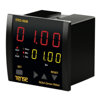
The Tense ERD-96M is a digital timer designed for industrial and commercial applications, offering precise control over various timing functions. It features a 2x4 digit, 7-segment LED display for clear visual feedback and is housed in a 96x96mm front panel, making it suitable for standard panel cutouts.

Function Description:

The ERD-96M operates as a versatile digital timer with START, RESET, and GATE inputs, along with two independent outputs (OUT1 and OUT2). It supports eight selectable operating modes, allowing for a wide range of timing applications. The timer can count down in hours, minutes, or seconds, providing flexibility for different time scales. A key feature is its ability to load the timer value and output status from the latest power failure after the initial power-on, ensuring continuity of operation. All settings are stored in an EEPROM memory, providing non-volatile storage and preventing data loss during power interruptions. The device accepts 230VAC inputs for START, RESET, and GATE functions.

Important Technical Specifications:

  • Panel Hole Size: 91x91mm
  • Display: 2x4 Digit 7 Segment display
  • Inputs: START / RESET / GATE (3x230 VAC, 0:0-50VAC, 1:150-240VAC). The GATE input inhibits countdown when active.
  • Outputs: OUT1, OUT2; 2xRelay (NO-O-NC), 250VAC, 2A, Resistive load.
  • Time Base: Selectable; 99:59 hours / 99:59 minutes / 599.9 seconds.
  • Modes: Selectable 8 different modes.
  • Supply Voltage: 100-240VAC, 50-60Hz.
  • Power Consumption: < 8VA.
  • Operating Temperature: -20 °C to 55 °C.
  • Operating Altitude: < 2000m.

Usage Features:

The ERD-96M offers extensive programming capabilities through its front panel. Users can set the timer value (t.SEt) for various modes, with options for seconds (000.0-599.9), minutes (00.00-99.59), and hours (00.00-99.59). For flashing modes (Mode 1), separate ON (t.on) and OFF (t.oFF) times can be configured. The time base can be selected as seconds, minutes, or hours (t.bAS). The device also allows selection of one of the eight operating modes (Out). A "Power-on Reset" (P.rES) feature determines whether the timer SET value is reset or if the timer value and OUT status are loaded from the latest power failure upon power-on. A fixed password (162) is required to access certain programming parameters. The front panel also includes a RESET function, activated by pressing for 2 seconds.

Operating Modes:

The timer supports eight distinct operating modes, each tailored for specific control scenarios:

  • Mode 0: Pulsed Delay, OFF with RESET: OUT1 & OUT2 turn ON after "t.SEt" when START is triggered (OFF→ON). START input cannot re-trigger the timer until a RESET. Outputs turn OFF when RESET is ON.
  • Mode 1: Flashing with START/RESET: OUT1 & OUT2 periodically flash (ON for "t.On", then OFF for "t.OFF") after START is triggered (OFF→ON). Outputs turn OFF when RESET is ON. For this mode, t.On and t.OFF accept minimum values of 000.1 seconds, 00.01 minutes, and 00.01 hours.
  • Mode 2: One Shot after ON and OFF: OUT1 & Out2 turn ON when START is triggered (OFF→ON or ON→OFF) and turn OFF after "t.SEt". START input can re-trigger when outputs are ON. Outputs turn OFF when RESET is ON.
  • Mode 3: OFF Delay: OUT1 & OUT2 turn ON when START is ON. They turn OFF "t.SEt" after START is triggered (ON→OFF). Outputs turn OFF when RESET is ON.
  • Mode 4: Follow & ON Delay: OUT1 is ON when START is ON. OUT2 turns ON "t.SEt" after START is ON. Both outputs turn OFF when START is OFF or when RESET is ON.
  • Mode 5: Delayed One Shot after OFF: OUT1 & OUT2 turn ON after "tA" and then OFF after "tB" when START is triggered (ON→OFF). START input cannot re-trigger before "tB" elapses. Outputs turn OFF when RESET is ON.
  • Mode 6: Chronometer - Count with START: OUT1 is ON and the timer counts up when START is ON. The timer freezes when START is OFF. OUT2 is ON when the timer reaches "T.SEt". The timer resets, and both outputs turn OFF when START is OFF after "T.SEt" elapses. Outputs turn OFF when RESET is ON.
  • Mode 7: Chronometer - Count with START, Reset with RESET: OUT1 is ON and the timer counts up when START is ON. The timer freezes when START is OFF. OUT2 is ON when the timer reaches "T.SEt". The timer resets, and both outputs turn OFF when RESET is ON.

Maintenance Features:

The device is designed for reliable operation but requires proper installation and attention to environmental conditions.

  • Wiring: It is recommended to use twisted pair and shielded signal cables. The shield should be connected to ground from the device side. All signal cables must be kept away from circuit breakers, devices/cables emitting electrical noise, and power cables to prevent interference.
  • Environmental Considerations: Precautions should be taken against humidity, vibration, pollution, and extreme temperatures (high/low) during installation to ensure optimal performance and longevity.
  • Fusing: A slow 250mA 250VAC fuse must be used on the supply input of the device for protection.
  • Cable Selection: Appropriate cables should be used for supply connections, and all safety regulations must be followed during installation.

The timer counts up for Modes 6 & 7 and counts down for all other modes. In all modes, counting is inhibited (or frozen) when the GATE input is ON.

Tense ERD-96M Specifications

General IconGeneral
BrandTense
ModelERD-96M
CategoryTimer
LanguageEnglish

Related product manuals