EasyManua.ls Logo

Tense TPM-04SH-DL - User Manual

Tense TPM-04SH-DL
14 pages
Print Icon
To Next Page IconTo Next Page
Loading...
Supports 3P4W connections.
Measures up to voltage harmonics 31st.
Measures up to current harmonics 31st.
RS485 Modbus RTU
It shows the powers of each phase (P1, P2, P3).
It shows the apparent powers of each phase (S1, S2, S3).
It shows the reactive powers of each phase (Q1, Q2, Q3 inductive and capacitive).
It shows power factors (PF) and cosφ values of each phases.
It shows the min., max. and ave. values of the phase-to-phase and phase-neutral voltages.
It shows the values of each phase (I1, I2, I3).
It shows total import and export active (ΣkWh) energies..
It shows total inductive and capacitive reactive (ΣkVArh) energies.
Relay output (adjustable).
Digital Input.
It shows voltage and current irregularity.
It show demands. (Current, Active/Reactive/Apparent Power)
You can delete energies and demands.
The menu is password protected.
TPM-04SH-DL
USER MANUAL
Tense Electric - Electronic
MADE IN TURKEY
Document Number: DK-0106-1
53 x 31mm Custom Design Glass LCD
Question and Answer IconNeed help?

Do you have a question about the Tense TPM-04SH-DL and is the answer not in the manual?

Overview

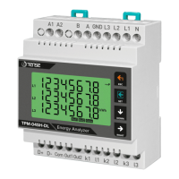
The Tense TPM-04SH-DL is a 3-phase, 4-wire energy analyzer designed for comprehensive monitoring of electrical parameters in industrial and commercial applications. This device provides detailed measurements of voltage and current harmonics up to the 31st order, offering a thorough analysis of power quality.

Function Description:

The TPM-04SH-DL measures a wide range of electrical parameters, including:

  • Voltage and Current Harmonics: Measures up to the 31st harmonic for both voltage and current, providing insights into power quality issues.
  • Power Measurements: Displays active power (P1, P2, P3), reactive power (Q1, Q2, Q3 inductive and capacitive), and apparent power (S1, S2, S3) for each phase.
  • Power Factor: Shows power factors (PF) and cosφ values for each phase.
  • Voltage and Current Values: Provides minimum, maximum, and average values for phase-to-phase and phase-neutral voltages, as well as current values (I1, I2, I3) for each phase.
  • Energy Monitoring: Tracks total import and export active (∑kWh) energies, and total inductive and capacitive reactive (∑kVArh) energies.
  • Demand Monitoring: Displays current, active, reactive, and apparent power demands.
  • Digital Input and Relay Output: Features a digital input and an adjustable relay output for control and alarm functions.
  • Irregularity Detection: Shows voltage and current irregularity.
  • Communication: Equipped with an RS485 Modbus RTU interface for remote communication and integration into larger systems.

Important Technical Specifications:

  • Operating Voltage: 85V - 240V AC
  • Operating Frequency: 50/60 Hz
  • Operating Power: <10VA
  • Operating Temperature: -20°C to 55°C
  • Voltage Inputs: 5V - 330V AC
  • Voltage Measurement Range: 5V - 330kV
  • Current Input: 10mA - 5.5A
  • Current Measurement Range: 10mA - 5,500A
  • Voltage/Current Accuracy: ±0.5%
  • Active Energy Accuracy: ±1%
  • Reactive Energy Accuracy: ±2%
  • Supported Connection: 3P4W
  • Current Transformer Ratio: 1 - 1000
  • Voltage Transformer Ratio: 1.0 - 999.9
  • Harmonic Voltage Measurement: 3 - 31
  • Harmonic Current Measurement: 3 - 31
  • Communication: RS485 MODBUS RTU
  • Baudrate: 1200bps - 19200bps
  • Relay Output: 2x 3A/250VAC (Resistive Load)
  • Digital Input: 1x 9V - 24VDC
  • Display: 53 x 31mm Custom Design Glass LCD
  • Protection Class: IP20
  • Panel Hole Sizes: 91mm x 91mm
  • Weight: <300Gr.
  • Operating Altitude: <2000 meters

Usage Features:

  • User-Friendly Interface: Features a 53 x 31mm custom design glass LCD for clear display of all measured values.
  • Intuitive Navigation: Utilizes four buttons (ESC, SET, DOWN, RIGHT) for easy navigation through menus and parameters.
    • ESC: Exits menus without saving, or returns to the main display (Figure-3) when not in a menu.
    • SET: Enters menus/parameters, records parameter changes, and removes from parameters.
    • DOWN: Facilitates fast progression between measured values outside the menu and changes values within menu parameters.
    • RIGHT: Displays measured values with details outside the menu and navigates between parameters within the menu, allowing transitions between steps and parameters.
  • Password Protection: The menu is password protected to prevent unauthorized changes.
  • Configurable Settings:
    • Current Transformer Ratio (CTR): Adjustable from 1 to 5000.
    • Voltage Transformer Ratio (VTR): Adjustable from 1.0 to 999.9.
    • RS485 Communication Settings: Configurable baud rate (1200-19200 bps), stop bits (1 or 2), data bits (8), parity (None, Even, Odd), and Modbus ID (1-247).
    • Relay Assignment: Relay outputs can be assigned tasks based on various parameters (Voltage, Current, Total Current, THD-V, THD-I, Power Factor, Voltage Unbalance, Current Unbalance, Digital Input, OFF) with adjustable functions (greater than/smaller than), values, delay times, and hysteresis values.
    • Backlight Duration: Adjustable from "Off" to 60 minutes.
  • Data Management: Allows deletion of energy and demand records.
  • Connection Diagrams: Provides clear 3P4W connection diagrams for easy installation.

Maintenance Features:

  • Cleaning: The device body can be cleaned with a slightly moist or dry cloth. Avoid using conductive or chemical cleaning agents that could harm the device. Ensure the device is disconnected from power and connections before cleaning.
  • Installation Considerations:
    • Maintain a 5 cm space behind the device after installation for proper ventilation.
    • Avoid installing the device in damp environments.
    • Install a key or circuit breaker close to the device for easy access by the operator.
    • Ensure connection cables are de-energized during assembly.
    • Use shielded or twisted-pair cables for non-network-connected input and output lines, keeping them away from high-power lines.
    • All assembly and electrical connections must be performed by qualified technical staff according to the instruction manual.
    • Feed cables must comply with IEC 60227 or IEC 60245 requirements.
  • Current Transformer Selection:
    • Ensure the current transformer value is higher than the maximum current drawn from the system.
    • A current transformer class of 0.5 is recommended.
    • Use different colored cables or assign cable numbers for current transformer output terminals to avoid complexity.
    • Keep current transformer output terminal cables away from remote high-voltage lines.
    • Secure current transformers to the busbar, cable, or rail to prevent rattling.
  • RS485 Communication: For cable lengths exceeding 100m in RS485 communication lines, connect a 120R resistor in parallel to the A-B (RS-485) terminal at the beginning and end of the communication line to prevent data loss.

Tense TPM-04SH-DL Specifications

General IconGeneral
BrandTense
ModelTPM-04SH-DL
CategoryMeasuring Instruments
LanguageEnglish

Related product manuals