EasyManua.ls Logo

Tequipment FLUKE i410 - User Manual

Tequipment FLUKE i410
9 pages
Print Icon
To Next Page IconTo Next Page
Loading...
PN 642733 December, 1996 1996 Fluke Corporation. All rights reserved. Printed in U.S.A. Product names are trademarks of their respective companies.
i410/i1010
AC/DC Current Clamp
Service Information
WWarning
To avoid electric shock:
Do not service this Current Clamp unless you are qualified to do so.
The service information provided in this document is for use by quali-
fied personnel only.
Always remove input signals from the Current Clamp before opening
the case.
Be careful when working with voltages that exceed 30V ac rms, 42.4V
pk, or 60V dc.
The Current Clamp is protected throughout by double insulation. When
servicing the Current Clamp, use only specified replacement parts.
Caution
If the Current Clamp is to be Calibrated, you must have a replacement
decal. See the Replacement Parts section for further details.
This Current Clamp contains parts that can be damaged by static dis-
charge. Follow the standard practices for handling static sensitive de-
vices.
Introduction
Service Information covers the following service-related areas for the i410/i1010 AC/DC Current
Clamps:
Product specifications
Required equipment
Performance test procedure and test values
Preparing for calibration
Calibration procedure
Reassembly procedure
Replacement parts
Usually, service information in this document applies to both models (i410 and i1010). Information ap-
plicable to only one model is so noted. For operating information, refer to the Instruction Sheet that came
with the Current Clamp.
®
Question and Answer IconNeed help?

Do you have a question about the Tequipment FLUKE i410 and is the answer not in the manual?

Overview

The Fluke i410/i1010 AC/DC Current Clamp is a device designed for measuring both alternating current (AC) and direct current (DC). It is intended for use by qualified personnel and comes with a one-year warranty covering defects in material and workmanship, excluding abuse, batteries, or damage from use outside its rated specifications. Service, repairs, and replacement parts are warranted for 90 days.

Function Description

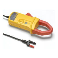
The primary function of the i410/i1010 Current Clamp is to measure AC and DC currents without breaking the circuit. It operates by clamping around a conductor, sensing the magnetic field generated by the current, and converting it into a voltage output signal. This output signal, typically 1 mV per amp, can then be read by a digital multimeter (DMM) or other compatible measuring device. The clamp is designed with double insulation for protection and includes a ZERO knob for adjusting the DC zero point, ensuring accurate readings.

Important Technical Specifications

The i410/i1010 Current Clamp has distinct specifications for its two models:

General Specifications (Table 1):

  • Operating Temperature: -10 to 50°C (14 to 122°F)
  • Storage Temperature: -20 to 60°C (-4 to 140°F)
  • Relative Humidity:
    • 0 to 95% (0 to 30°C)
    • 0 to 75% (30 to 40°C)
    • 0 to 45% (40 to 50°C)
  • Altitude:
    • Operating: 0 - 2000m
    • Non-operating: 0 - 12000m
  • Battery Type: 9V (alkaline)
  • Battery Life: 60 hours typical (continuous with alkaline)
  • Safety: Double Insulation, 600V, CAT. III
  • Current x Hz Product: ≤ 240,000
  • Output Signal: 1 mV per amp dc or ac
  • Working Voltage: 600V CAT. III maximum at input
  • Maximum Conductor Size:
    • 1 ea. 30 mm (1.18 in.) diameter
    • 2 ea. 25 mm (0.98 in.) diameter
  • Load Impedance: ≥1 MΩ, ≤100 pF
  • Temperature Coefficient: +/-(0.05 x accuracy per °C (0-18°C, 28-50°C))
  • Size: 209 x 78 x 48 mm (3.09 x 8.21 x 1.87 in.)
  • Weight: 0.5 kg (17.6 oz.)

Range and Accuracy Specifications (Table 2):

i410 Model:

  • Specified Current Range: 1-400A ac rms*, 1-400A dc
  • Usable Current Range: 0.5-400A
  • DC Accuracy (zero adjusted, conductor centered): 3.5% + 0.5A (0 - 400A)
  • AC Accuracy: 3.5% + 0.5A, 45 - 400 Hz, Crest Factor ≤ 3. (1 - 400A)
  • Bandwidth: 3 kHz
    • *With a true-rms DMM, the minimum ac current is limited to the low end of the specified mV ac range.

i1010 Model:

  • Specified Current Range: 1-600A ac rms*, 1-1000A dc
  • Usable Current Range: 0.5-1000A
  • DC Accuracy (zero adjusted, conductor centered): 2.0% + 0.5A (0-1000A)
  • AC Accuracy:
    • 2.0% + 0.5A, 45 - 400 Hz, Crest Factor ≤ 3.
    • 3.0% + 0.5A, 400 Hz - 2 kHz sine wave. (1 - 600A)
  • Bandwidth: 10 kHz
    • *With a true-rms DMM, the minimum ac current is limited to the low end of the specified mV ac range.

Usage Features

  • Ease of Use: The clamp is designed for straightforward operation, with a power on/off button and a ZERO knob for DC zero adjustment.
  • Conductor Centering: For optimal accuracy, especially in DC measurements, the conductor should be centered within the clamp jaws.
  • Safety: The device features double insulation and is rated for 600V CAT. III, emphasizing user safety during measurements.
  • Battery Operation: Powered by a 9V alkaline battery, offering typical continuous operation for 60 hours. A battery LED indicates the battery status.

Maintenance Features

  • Performance Test: A comprehensive performance test procedure is outlined to verify that the Current Clamp is working properly and meets specifications. This includes a Battery LED Test and Measurement Accuracy Tests for both DC and AC current.
  • Calibration and Adjustment: The manual provides detailed steps for calibration, including:
    • Battery Indicator Calibration: Adjusting VR4 to set the low battery LED threshold.
    • DC Zero Calibration: Adjusting VR3 and using the ZERO knob (VR2) to ensure accurate zero readings.
    • DC Amps Function Calibration: Adjusting VR5, VR6, and VR1 to fine-tune DC current measurement accuracy across the range.
    • AC Amps Function Check: Verifying AC current measurement accuracy against specified limits.
  • Replacement Parts: A list of replacement parts with part numbers is provided, including decals, battery door, case components, PCB assembly, jaw spring, and output cable assembly. This facilitates repairs and ensures the availability of genuine components.
  • Decal Removal for Calibration: Calibration requires the removal of the top case decal to access adjustment potentiometers. A new decal should be installed after calibration.
  • Static Sensitive Devices: The clamp contains parts susceptible to static discharge, requiring standard handling practices for static-sensitive devices during service.
  • Qualified Personnel: All service and calibration procedures are intended for qualified personnel to ensure proper handling and to avoid electric shock. Input signals must be removed before opening the case.

Tequipment FLUKE i410 Specifications

General IconGeneral
BrandTequipment
ModelFLUKE i410
CategoryTest Equipment
LanguageEnglish