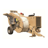
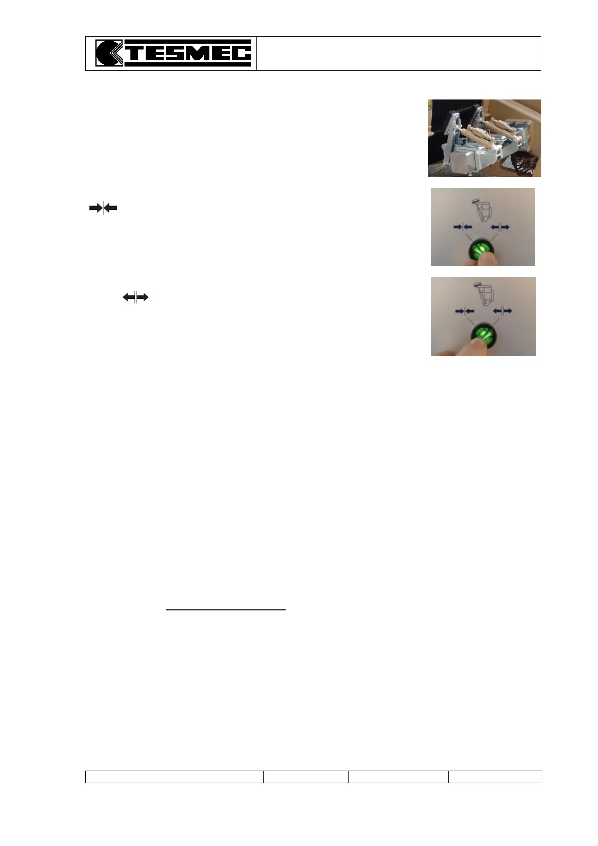
When the machine is set with hydraulically connected capstan (selector table 1, pos.42 rightwards) the
selector (table 1, pos.21) operate on both the rope clamps.
4.16 POINTS TO REMEMBER
a. The pressure of the feeding circuit (table 1, pos. 31 and 37) must be higher than 22 bar – 320 psi:
otherwise, the stationary brakes will be damaged.
b. Adjust the pull of the reel elevators with hydraulic head (table 1, pos. 24 and 26) at minimum
indispensable value: otherwise, the hydraulic oil will be uselessly heated and dangerous counter
pulls may arise.
c. In hot climates, during stoppages, let the Diesel engine running with the radiator fan (table 1, pos. 28)
engaged at maximum speed.
d. Before beginning the works, check the levels.
e. Do not work with the hydraulic oil temperature higher than 80°C.
f. After an emergency intervention of the negative safety brake, verify the condition of the brake
discs.
g. Remember to use the values indicated on the “puller” scale for the recovery phases and those
indicated on the “tensioner” scale for the stringing phases.
h. When using the machine as tensioner, position the 2 automatic pull limiting devices
(table 1, pos. 30-36) on the maximum bottom of scale value, to avoid dangerous stopping.
This operation is absolutely indispensable when the tensioner machine works with a puller without
automatic pull limiting device.
i. The connecting operations of the mechanical reduction gears (table 2, pos. 21-22 and/or table 3, pos. 8)
have to be made only with stopped machine.
4.17 END OF OPERATIONS
At the end of the operations, discharge the ropes-conductors tension using the control levers
(table 1, pos. 34 and 40) in releasing position.
Then turn off the engine operating on the ignition key.
 Loading...