EasyManua.ls Logo

Texecom Reflex

Texecom Reflex
2 pages
To Next Page IconTo Next Page
Loading...
3 FALSE ALARM PROTECTION
Design: Noise reduction circuits with maximum ground plane.
RF Immunity: No false alarms from 80MHz to 1GHz at 50V/m,
equivalent to a 700W uniform transmitter at 3m (10ft).
Complies with BS EN 61000-4-3 : 1997.
Electrostatic Discharge: No false alarm up to 8kV.
Complies with BS EN 61000-4-2 : 1995.
Fast Transient Immunity: No false alarm up to ±1kV.
Complies with BS EN 61000-4-4 : 1995.
High Energy Transient
Immunity: No false alarm up to ±1kV.
Complies with BS EN 61000-4-5 : 1995.
Conducted RF
Susceptibility: No false alarms at 10Vrms.
Complies with BS EN 61000-4-6 : 1996.
Conducted Emissions: Complies with EN 55022 Class B.
Radiated Emissions: Complies with EN 55022 Class B.
EMC: Independently certified to EN 50130-4 : 1996.
Pulse Count: Adjustable Pulse Count. Internal link to select.
2 ENVIRONMENTAL1 PHYSICAL
4
8 COVERAGE AT 2m7 MOUNTING HEIGHT AND
SETTINGS
6 ANGLING THE DETECTOR5 COVERAGE AND PICK-UP
ALARM
12V
0V TAMPER
<24VDC
50mA, 18
(N/C)
<24V
DC
50mA
(N/C)
9-16V
DC
10mA @ 12VDC
1.5m
(4'10")
2.5m
(8'4")
3.1m
(10'0")
2.0m
(6'7")
-35°C (-31°F) to +60°C (+140°F)
125g (4.5oz) approx.
-35°C (-31°F) to +55°C (+131°F)
63mm
(2.5)
40mm
(1.6)
90mm
(3.6)
2.5mm (0.1) ABS
0.3 - 3.0m/s
QUALITY ASSURANCE
WARRANTY
10 year replacement warranty.
The Reflex is designed to detect the movement of an intruder and activate
an alarm control panel. As the Reflex is not a complete alarm system, but only a
part thereof, Texecom cannot accept responsibility or liability for any damages
whatsoever based on a claim that the Reflex failed to function correctly.
Due to our policy of continuous improvement Texecom reserves the right
to change specification without prior notice. All specifications are measured at
20˚C (68˚F).
Document Ref: REF/EU/1.0-7
©1994 - 2004 Texecom Ltd
Certificate Number: FM 35285
INS 156-4
LED ON
LED OFF
PULSE COUNT
1
2
3
www.texe.com
BEST
SELLING PIR
1 - 10ft/s
DO NOT TOUCH
FAST
NORMAL
SLOW
P assive Infrared Detector
INSTALLATION INSTRUCTIONS
www.texe.com
WINNER
THANK YOU FOR VOTING TEXECOM
Ask your distributor today for the new Texecom full colour Product Guide.
Question and Answer IconNeed help?

Do you have a question about the Texecom Reflex and is the answer not in the manual?

Texecom Reflex Specifications

General IconGeneral
TechnologyPassive Infrared (PIR)
TypePIR Detector
Detection Range12m
Field of View90 degrees
Power SourceBattery
Battery Life3 years (typical)
Tamper ProtectionYes

Summary

Environmental Specifications

Operating Temperature Range

Device operating temperature from -35°C (-31°F) to +60°C (+140°F).

Component Temperature Range

Component operating temperature from -35°C (-31°F) to +55°C (+131°F).

False Alarm Protection Features

RF Immunity

No false alarms from 80MHz to 1GHz at 50V/m.

Electrostatic Discharge Immunity

No false alarm up to 8kV according to BS EN 61000-4-2.

Fast Transient Immunity

No false alarm up to ±1kV according to BS EN 61000-4-4.

High Energy Transient Immunity

No false alarm up to ±1kV according to BS EN 61000-4-5.

Conducted RF Susceptibility

No false alarms at 10Vrms according to BS EN 61000-4-6.

Conducted Emissions

Complies with EN 55022 Class B.

Radiated Emissions

Complies with EN 55022 Class B.

EMC Compliance

Independently certified to EN 50130-4:1996.

Pulse Count Setting

Adjustable pulse count, internal link to select FAST, NORMAL, or SLOW.

Mounting Height and Coverage

Detection Coverage Patterns

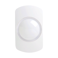
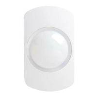
Diagrams illustrating detection coverage at different mounting heights (1.5m to 3.1m).

Lens System and Placement

Lens Components

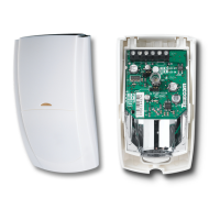
Details on the lens retainer and facets of the detector.

Location Considerations

Advice on detector placement to avoid false alarm sources.

Mounting Instructions

Indoor Use Mounting

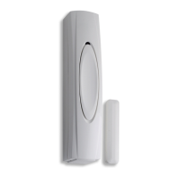
Specific mounting instructions for indoor environments.

Stable Surface Mounting

Instructions for mounting the detector on a stable surface.

Detector Knockouts

Diagram showing knockouts for wiring and sealing holes.

Mounting Without Brackets

Illustration of mounting the detector directly without using brackets.
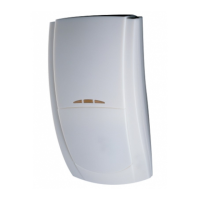
Related product manuals