Instruction manual EHP 3 page 12
____________________________________________________________________________
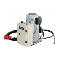
4. Description of the electro-hydraulic pump
4.1. Description of components
The electric-hydraulic pump type EHP 3 consists of the following components:
picture 1
Pos.-No. 4
Pos.-No. 1
Pos.-No. 5
Pos.-No. 3
Pos.-No. 2
Pos.-No. 9
Pos. No. 7
Pos.-No 6
(The picture does not correspond in all details with the delivered version)
Pos.-No. 8
Pos. 10
Table 1
Pos.-No. Description Function Reference
1 Power switch Switch for the power supply pp 12, 14
2 Socket To connect the safety foot switch pp 12, 14
3 Power control lamp Lamp that indicates that the pump is ready
for service
p 12
4 Oil filler Cap screw to oil reservoir pp 12, 16
5 Oil-level control glass Indicates the amount of hydraulic oil in the
System
pp 12, 16
6 Oil release screw Screw necessary to change the hydraulic oil p 12
7 Power supply plug Plug for rotary current pp 12, 14
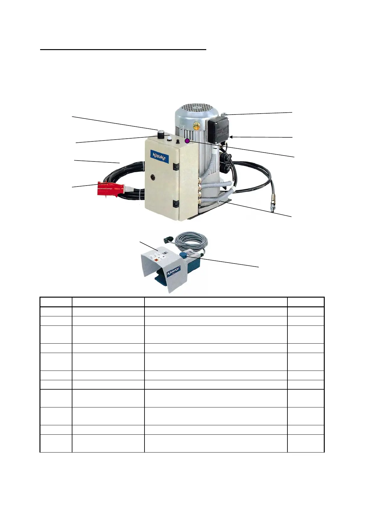
8 Safety foot switch Foot actuated 3-phase switch to operate the
unit
pp 12, 13
9 Hydraulic hose Steel armed high pressure hydraulic hose pp 12, 13,
14
10 Handle Carrying grips to move the unit p 3
11 Reset button Reactivates the foot switch after activating
the 3
rd
phase
pp 13
 Loading...