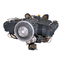
SECTION 5 LYCOMING OPERATOR’S MANUAL
MAINTENANCE PROCEDURES O-320 SERIES
NOTE
On installations employing full flow oil filters, this step is not practical at this time, but
should be observed at the 50-hour inspection, not to exceed four (4) months between oil
changes.
(1) Non-Adjustable Oil Pressure Relief Valve – The function of the oil pressure relief valve is to
maintain engine oil pressure within specified limits. The valve, although not adjustable, may be
controlled by the addition of a maximum of nine STD-425 washers under the cap to increase
pressure or the use of a spacer (Lycoming P/N 73629 or 73630) to decrease pressure. A
modification on later models has eliminated the need for the spacers. Particles of metal or other
foreign matter lodged between the ball and seat will result in faulty readings. It is advisable,
therefore, to disassemble, inspect and clean the valve if excessive pressure fluctuations are noted.
(2) Oil Pressure Relief Valve (Adjustable) – The adjustable oil relief valve enables the operator to
maintain engine oil pressure within the specified limits. If pressure under normal operating
conditions should consistently exceed the maximum or minimum specified limits, adjust the
valve as follows:
With the engine warmed up and running at approximately 2000 RPM, observe the reading on
the oil pressure gage. If the pressure is above maximum or below minimum specified limits, stop
engine and screw the adjusting screw outward to decrease pressure or inward to increase
pressure. Depending on installation, the adjusting screw may have only a screw driver slot and is
turned with a screw driver; or may have the screw driver slot plus a pinned .375-24 castellated
nut and may be turned with either a screw driver or a box wrench.
4. CYLINDERS. Although the complete procedure for disassembly and reassembly is given here, it is
recommended that, as a field operation, cylinder maintenance be confined to replacement of the entire
assembly. Valve replacement should be undertaken only as an emergency measure.
a. Removal of Cylinder Assembly.
(1) Remove exhaust manifold.
(2) Remove rocker box drain tube, intake pipe, baffle and any clips that might interfere with the
removal of the cylinder.
(3) Disconnect ignition cables and remove the bottom spark plug.
(4) Remove rocker box cover and rotate crankshaft until piston is approximately at top center of the
compression stroke. This is indicated by a positive pressure inside of cylinder tending to push
thumb off of bottom spark plug hole.
(5) Slide valve rocker shafts from cylinder head and remove the valve rockers. Valve rocker shafts
can be removed when the cylinder is removed from the engine. Remove rotator cap from exhaust
valve stem.
(6) Remove push rods by grasping ball end and pulling rod out of shroud tube. Detach shroud tube
spring and lock plate and pull shroud tubes through holes in cylinder head.
5-6
 Loading...