EasyManua.ls Logo

TFT Ball Intake Valve - User Manual

TFT Ball Intake Valve
8 pages
Print Icon
To Next Page IconTo Next Page
Loading...
This instruction manual is intended to familiarize firefighters and maintenance
personnel with the operation, servicing and safety procedures associated with
the Ball Intake Valve.
This manual should be kept available to all operating and maintenance
personnel.
MANUAL: Ball Intake Valve™
WARNING
Read instruction manual before use. Operation of this device without
understanding the manual and receiving proper training is a misuse of this
equipment. A person who has not read and understood all operating and safety
instructions is not qualified to operate the Ball Intake Valve.
OPERATING RANGE:
Pressure Max 250 PSI
Pressure Min Full Vac.
Hydrostatic
Proof Test:
900 PSI
INSTRUCTIONS FOR SAFE OPERATION AND MAINTENANCE
LIA-200 December 9, 2005 Rev 08©Copyright Task Force Tips, Inc. 2002-2005
A1306
®
1-219-462-6161
1-800-348-2686
www.tf t.com
TASK FORCE TIPS, Inc.
2800 E. Evans Ave, Valparaiso, IN 46383-6940 USA
800-348-2686 219-462-6161 Fax 219-464-7155
MADE IN USA •www.tft.com
Question and Answer IconNeed help?

Do you have a question about the TFT Ball Intake Valve and is the answer not in the manual?

Summary

Safe Operation and Maintenance Instructions

Critical Safety Warning

Read manual and receive training before operation to avoid misuse and injury.

Safety Information and Signal Words

Signal Word Definitions

Definitions for DANGER, WARNING, and CAUTION hazard indicators.

General Safety Precautions

Crucial safety advice regarding pressure, hose kinks, and proper connection.

General Information and Installation

Material Properties and Use

Details on corrosion resistance, salt water use, and material properties.

Installation Procedures

Instructions for mounting the valve on trucks and switching the handwheel side.

Valve Operation and Pressure Relief

Operating the Ball Intake Valve

Guidance on using the intake elbow, position indicator, and air vent/drain.

Pressure Relief Valve Details

Information on setting pressure, performance curves, and relief valve operation.

Drawings and Parts Lists

Exploded View Diagram

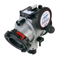
Detailed diagram illustrating the components of the Ball Intake Valve.

Parts Lists

Ball Intake Valve Parts List

Comprehensive list of parts for the Ball Intake Valve with part numbers.

Relief Valve Parts List

Specific parts list for the pressure relief valve components.

Maintenance and Performance

Maintenance Procedures

Guidelines for regular cleaning, inspection, lubrication, and part replacement.

Pressure Loss Characteristics

Graph illustrating pressure loss for 4-inch and 5-inch couplings at various flow rates.

Warranty Information

Limited Express Warranty

Details on TFT's five-year warranty, limitations, and exclusions.

TFT Ball Intake Valve Specifications

General IconGeneral
CategoryControl Unit
BrandTFT
Flow DirectionBi-directional
TypeBall Valve
MaterialBrass
Connection TypeThreaded, Flanged, or Socket Weld
Ball MaterialBrass
Seat MaterialPTFE
OperationManual
End ConnectionThreaded, Flanged, or Socket Weld