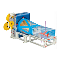
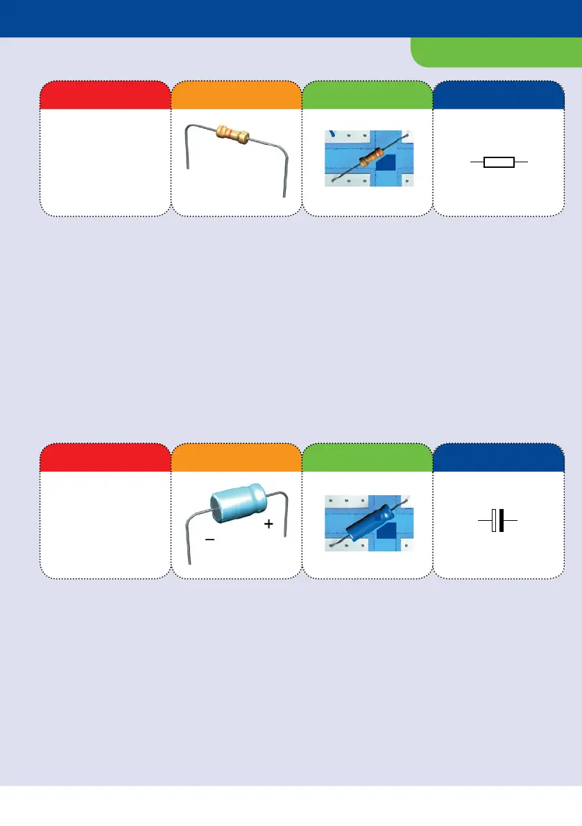
EQUIPMENT
effect. You can tell how large a resistor is
by looking at the little colored rings
printed on the component.
The various resistors in your kit can be
distinguished as follows:
Ω yellow-violet-brown
. kΩ orange-orange-red
kΩ red-red-orange
kΩ brown-black-yellow
kΩ red-red-yellow
In this kit, you will find a 10-µF capacitor
and a 100-µF one. The capacitance value is
printed directly on it. For your
experiments, you will be using so-called
electrolytic capacitors, which have a plus
and a minus mark.
Note: The electrolytic capacitors always
have to be installed the right way around,
exactly as shown in the circuit diagram.
In electronics, it’s a common problem that
there might be too much current flowing
— which can be dangerous for certain
electronic components. Light-emitting
diodes — miniature electronic lights —
can overheat, for example, and be
destroyed if they get too much current.
That’s why you need resistors, which act
like little “current brakes.” Their ability to
put the brakes on current is indicated in
ohms (Ω) and kilohms (kΩ). The more ohms
a resistor has, the greater its braking
Capacitors are able to store electric
current, just like a battery. Their
capacitance, or how much current they
can store, is indicated in “farads.” Usually,
though, 1 farad is much too much. That’s
why you typically work with a much
smaller unit of measure, the “microfarad”
— one millionth of a farad! The
abbreviation for microfarad is “µF” (with
that first symbol being the Greek letter
“mu,” short for “micro” or “one millionth”).
Resistors
Electrolytic
capacitors
Component Illustration Pictorial Representation Schematic Symbol
Component Illustration Pictorial Representation Schematic Symbol
2.2 MΩ
100 nF
CDS
NTC
GND
+5V...+9V
D0
D1
D2
D3
Digit
BC
EE
n
p
n
BC
EE
p
n
p
10 µF
PWM
Uin
D0 Din
D1
D2
D3
D4
D5
GND
Beep
Start
Reset
+5V
GND
+9V
B
C
T
E
B
C
E
R
3.3 kΩ
10 k
10 F
C
LED
100 nF
CA
AC
UV
ST
O
P
R
C
Ta
A
CA
+
+
–
9 V
–+
M
–+
NTC
PHT
+ 5V
GND
D0
D1
D2
D3
Dig
IR
PWM
D0
D1
D2
D3
D4
D5
GND
Uin
Din
Beep
Start
Reset
+5V
GND
+9V
Mikrocontroller
CE
CE
R5
. kΩ
C1
µF
+
 Loading...