terminal), meaning no current flows, with
the gate at the collector (C) staying shut
and blocking the path of the water to the
emitter (E). If water does flow in the small
base channel (B), then the gate at the
collector terminal opens up and a current
flows from the collector (C) to the emitter
(E) that is much stronger than the base
current (B)!
So now the transistor is switched on, and
current flows between the collector (C)
and the emitter (E).
The transistor is not just capable of
turning on and off, though. It can also
become more or less conductive. It can use
smaller current to influence larger ones,
which can be used to amplify small
signals.
In the model, we can picture that as small
waves in the base channel turning into
larger ones in the collector-emitter
channel.
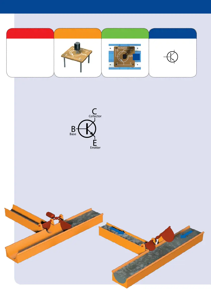
Transistors are used for switching and
amplifying electrical currents and
voltages. Each of the two transistor
modules in your kit has three terminals:
> Collector (C)
> Base (B)
> Emitter (E)
Always be sure to insert the sensitive
transistor the right way around — exactly
as shown in the circuit diagram!
You can understand the way a transistor
works by picturing a model with gates
that are controlled by water: First, no
water flows in base channel B
(corresponding to the transistor’s base
Transistor
Module
Component Illustration Pictorial Representation Schematic Symbol
2.2 MΩ
100 nF
CDS
NTC
GND
+5V...+9V
D0
D1
D2
D3
Digit
BC
EE
n
p
n
BC
EE
p
n
p
10 µF
PWM
Uin
D0 Din
D1
D2
D3
D4
D5
GND
Beep
Start
Reset
+5V
GND
+9V
B
C
T
E
B
C
E
R
3.3 kΩ
10 k
10 F
C
LED
100 nF
CA
AC
UV
ST
O
P
R
C
Ta
A
CA
+
+
–
9 V
–+
M
–+
NTC
PHT
+ 5V
GND
D0
D1
D2
D3
Dig
IR
PWM
D0
D1
D2
D3
D4
D5
GND
Uin
Din
Beep
Start
Reset
+5V
GND
+9V
Mikrocontroller
CE
CE
T2
E
E
B
B
C
C
 Loading...