EQUIPMENT
Light-emitting
diodes
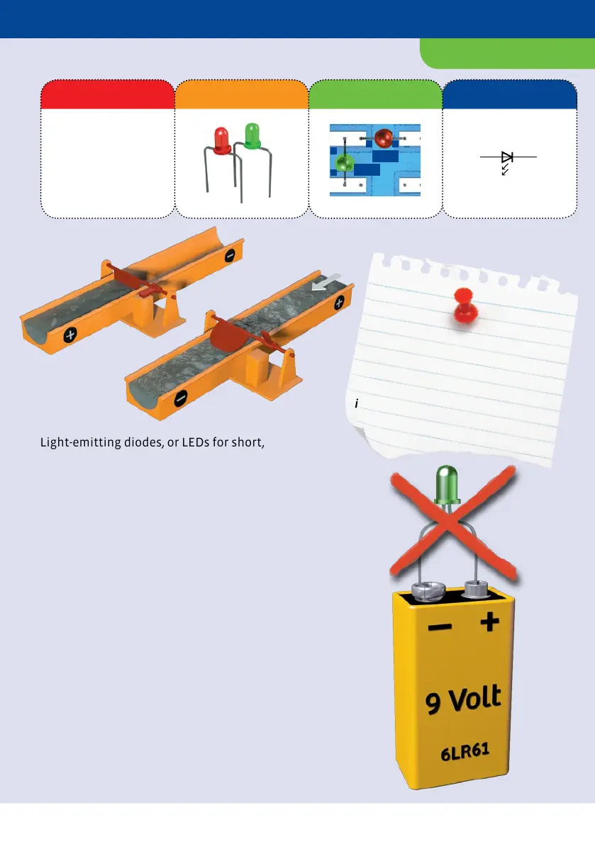
Component Illustration Pictorial Representation Schematic Symbol
Light-emitting diodes, or LEDs for short,
are small, sensitive components used to
signal a switch state. For example, an LED
will let you see whether a piece of
equipment is switched on or whether an
alarm has been triggered. LEDs have
terminals of two different lengths. The
shorter one is called a cathode (C), and the
longer one is an anode (A).
LEDs and other diodes have two different
poles, meaning that they only work in one
direction. When turned the wrong way,
they won’t let current through and they
also won’t light up.
Diodes work similarly to the model with
the water and the gate. If the current
comes from the wrong direction, the
mechanism prevents the water from
flowing through.
If the water comes from the other
direction, the gates open up and the water
flows through. That corresponds to an LED
with its poles turned the right way.
Safety note
Never hold light-emitting diodes
directly against a battery to see
whether they light up. They would
immediately break!
2.2 MΩ
100 nF
CDS
NTC
GND
+5V...+9V
D0
D1
D2
D3
Digit
BC
EE
n
p
n
BC
EE
p
n
p
10 µF
PWM
Uin
D0 Din
D1
D2
D3
D4
D5
GND
Beep
Start
Reset
+5V
GND
+9V
B
C
T
E
B
C
E
R
3.3 kΩ
10 k
10 F
C
LED
C
A
CA
+
+
–
9 V
–+
M
–+
NTC
PHT
+ 5V
GND
D0
D1
D2
D3
Dig
IR
PWM
D0
D1
D2
D3
D4
D5
GND
Uin
Din
Beep
Start
Reset
+5V
GND
+9V
Mikrocontroller
CE
CE
LED1
LED2
C
A
A
C
A
A
C
C