©
The GigRig ltd Jan 2009
All rights reserved. Design rights claimed. Moral rights asserted. © May 2008 Page 3
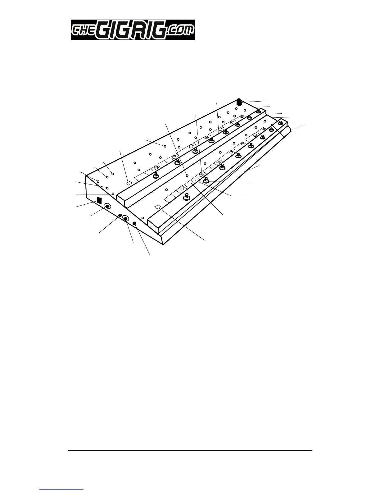
2. TheGigRig Main Diagram
1. Strong metal housing (lid and tray construction)
2. Foot switch (16 strong foot or hand operated switches)
3. Control mini switches (10 mini switches) Replaceable.
4. Effects loops mini switches (6 mini switches) Replaceable.
5. Mode toggle switch bottom rail (two modes for each rail)
6. Phase Switch (In phase when pushed in)
7. Output 2 (isolated) (Jack Socket, transformer output 1KV isolation)
8. Expand connection (communicate with another GigRig)
9. Output 1 (Jack Socket, primary output)
10. 9V input (use TheGigRig supply only)
11. Output LED (on when output is live)
12. Post volume level indicator (Brightness shows volume setting)
13. Post volume active indicator (on when post amp is in the signal path)
14. Remote switch 1 LED (normally closed when LED is off)
15. Remote switch 2 LED (normally open when LED is off)
16. Mode toggle switch top rail (single or multi patch for top rail)
17. Effects loop LED (on when effect is in the signal path)
18. Pre-set LED (on when patch is selected)
19. Post volume control (Volume control for each patch)
20. Foot switch rail (Strong Chrome rail for stomping on)
21. Pre Volume knob and LED (master volume. LED is on when in use)
22. AUX. output (on side) (used for silent tuning or signal routing)
23. Guitar input (on side) (Input from guitar or other instruments)
24. 9V out (on side) (Supplies protected power to your effects pedals)
25. Bypass select switches (Selects true or buffered bypass, select out 2 off)
13
14