36
Number Name SKu
1 C
ollection Chamber 160277
2 Handle 160241
3 Intake Distributer 160242
4 Filter Foam 160243
5 Clamp Replacement Kit 160244
6 Suction Hose – 13’ x 1.5” 160246
7 Discharge Hose – 8’ 160247
8 Gravel Nozzle 160248
9 String Algae Nozzle 160249
10 Filter Retainer Plate 160266
11 Suction Extension Tube (Black) 160267
12 Suction Extension Tube (Clear) 160268
13 Narrow Nozzle 160269
15 Wide Nozzle 160271
16 Wheel 160272
17 Debris Bag 160273
18 Vacuum Seal Replacement Kit 160274
19 Vacuum Distributer Assembly 160275
Not Shown Discharge Hose Extension Kit
(Contains Debris Bag, 8’ Discharge
Hose & Coupler)
160276
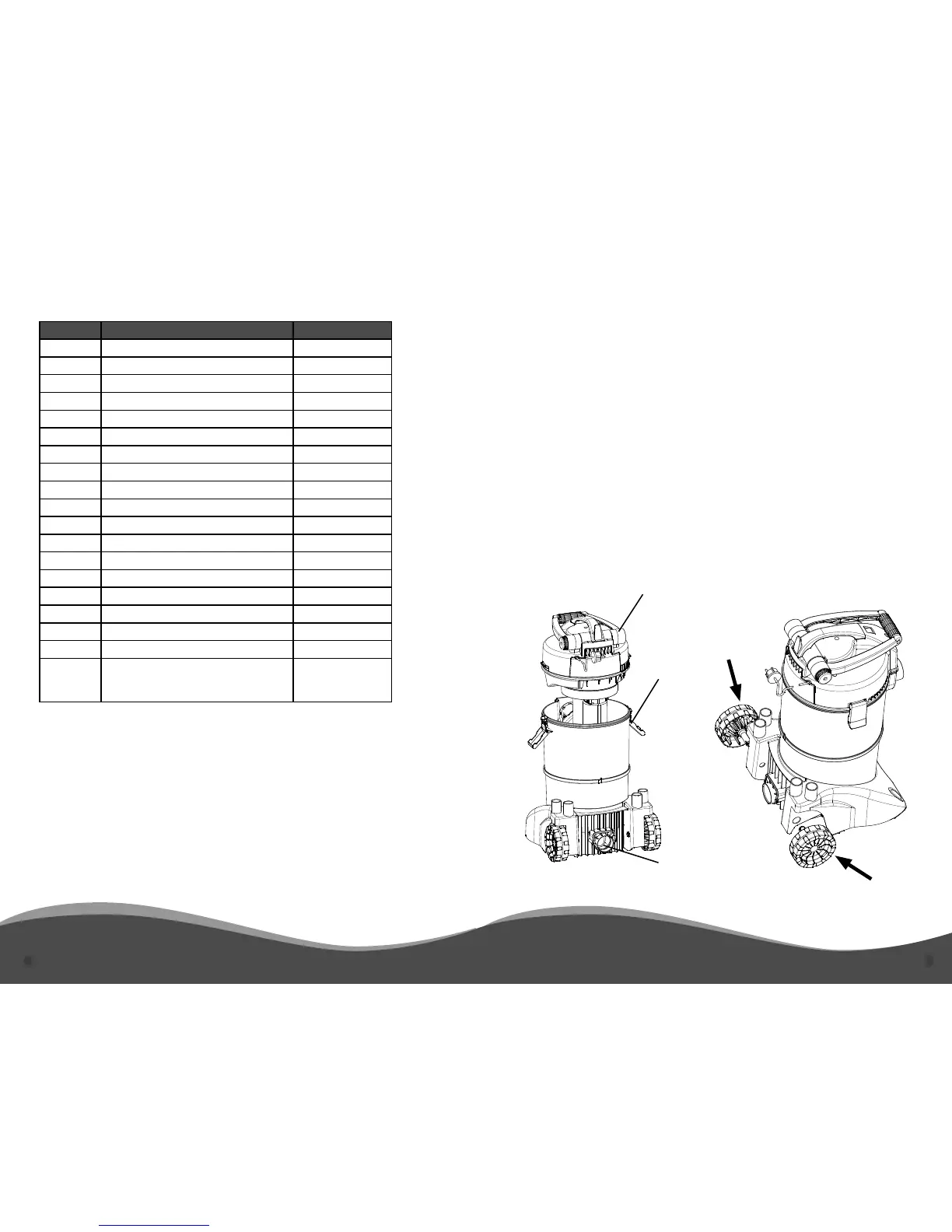
SETUP
NOTE: Components referenced with a number in parenthesis can be found in Diagram 1
on page 7 of this manual.
1) Unlock the Motor Housing Clamps (5) and remove the Motor Housing. (Figure 1)
2) Remove any stored parts from the Collection Chamber (1).
3) Replace the Motor Housing and relock Motor Housing Clamps (5).
4) Attach the Wheels (16) at the rear base of the ClearVac™. (Figure 2)
5) Insert Suction Hose (6) into the Intake Distributer (3) on the front of the Collection Cham-
ber (1). Attach desired nozzle to opposite end of Suction Hose (6).
6) Insert the Discharge Hose (7) into the Drain Opening (Figure 1) on the rear of the Collec-
tion Chamber (1). Lay Discharge Hose (7) at to assist in draining. When desired, attach the
Debris Bag (17) to the end of the Discharge Hose (7) to catch large debris.
NOTE: The ClearVac™ must be connected directly to a GFCI outlet. If using an
extension cord use only a 10 or 12 gauge outdoor rated extension cord no longer
than 50’. The use of an improper extension cord will cause damage to the unit
and will void the warranty.
Figure 1 Figure 2
MotorHousing
DrainOpening
MotorHousing
Clamp(5)
AVAILABLE PARTS
 Loading...