3
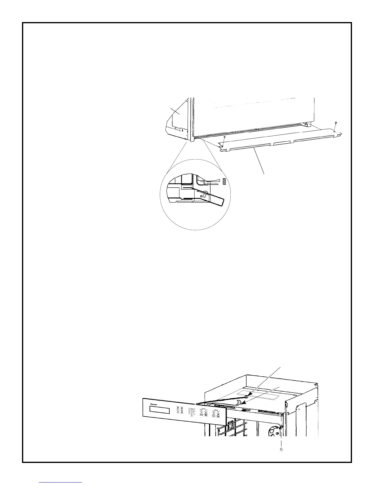
View 'A'
Side View
'A'
Remove the two screws from
the bottom trim, pull it forward
and remove it.
Install the lower vent trim and
secure with (2) screws provided,
one at each top end corner of
the trim. The sheet metal bot-
tom of the oven should be un-
der the trim, except for the sec-
tion at the center. To install the
screws, open the door. The
holes are visible at each end be-
low the left and right hinges.
Place and tighten screws.
See Fig. 2 View 'A'.
FIGURE 2.
a) Remove the screws from the bottom of
the control panel frame and pull the top
of the panel forward to unsnap it from
the subpanel.
b) Disconnect the ribbon cable and plug, and
remobe the panel.
Figure 3
Connectors Plug P2
Ribbon Cable
Bottom Trim
Side
Trim
Bottom Screw
REMOVE FRONT OVEN TRIMS:
1) REMOVE BOTTOM TRIM (4 screws).
2) REMOVE SIDE TRIMS (4 screws on each trim).
3) REMOVE CONTROL PANEL. (4 screws) REMOVE RIBBON AT TOUCH CONTROL
BOARD. DISCONNECT PLUG P2 AT TOUCH CONTROL BOARD.
NOTE: To remove the ribbon cable from the
relay board connector, lift the ends of the lock-
ing strip and raise the strip, then remove the
end of the ribbon cable.
 Loading...