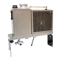
The document is a resource manual for the THERMAFLOW SS Model SS675 Transport Hydraulic Cooling System, providing installation guidelines, operating procedures, and a parts breakdown.
The THERMAFLOW SS675 assembly is designed to cool and filter hydraulic oil, which is essential for operating a hydraulic system. The cooling process involves forcing air across cooling fins on a heat exchanger. The system offers two fan motor options: electric or hydraulic. The electric fan motor option utilizes a 12VDC cooling fan, controlled by a manual, weather-tight toggle switch. This switch can be wired "hot" (always on) or grounded through an air-operated on/off switch. Wiring through the air switch provides automatic fan control, cycling the fan "ON" when the PTO (Power Take-Off) is engaged and "OFF" when disengaged. This automatic control also allows the operator to turn off the fan in cold weather to quickly raise oil temperature. If the fan switch is wired "hot" without automatic control, there's a risk of overheating the hydraulic oil if the fan is not manually turned "ON." The hydraulic fan motor option features a fixed pressure-compensated flow control, which automatically cycles the fan "ON" when the hydraulic system is running and "OFF" when not running. This option comes pre-plumbed from the factory. The THERMAFLOW system is custom-engineered for specific product pump applications, requiring different speed and power. Operating the system beyond its designed capacity can lead to overheating and/or component damage.
Important Technical Specifications:
- Max Flow Rate: 50 gpm
- Max Pressure: 5000 psi (with optional high-pressure relief valve)
- Reservoir Capacity: 7.2 gallons
- Weight: 100 lbs
- Suction Line Recommendation: 1.5-2 inches
- Pressure Lines Recommendation: 1 inch
- Warranty: 2 years
Installation Guide:
The Model SS675 is designed to be mounted behind the truck cab, across the frame rail sides. Two mounting options are available, including a "No Drill Option." A minimum of 4 inches of clearance on both sides of the unit is required for proper airflow.
PTO & Hydraulic Pump Installation:
The PTO should be installed to the transmission, and the hydraulic pump mounted according to the instructions provided with the PTO. For direct mount hydraulic pump/PTO combinations, it is crucial to lubricate the pump splines with heavy grease (STAC Inc P/N 300980) to prevent premature wear on the PTO and pump shafts. Greaseable shaft options are also available from MUNCIE and CHELSEA, allowing spline lubrication without removing the pump from the PTO.
Electrical Wiring (for Electric Fan Models):
Two wiring options are available for the 12VDC fan motor:
- Fan Switch Wired Hot: This option allows the fan to be turned on at any time, regardless of whether the tractor is running.
- RED WIRE: Connect to the positive (+) 12VDC battery terminal (20 Amps) through the circuit breaker (150153) provided in electrical kit (150525).
- BLACK WIRE: Connect to the truck frame or the negative (-) battery terminal.
- Note: Power supply should be taken directly from a battery post or similar high current location.
- Fan Switch Grounded Through an Air Switch: This option allows the fan to be turned on only when the PTO is engaged, providing automatic fan operation.
- RED WIRE: Connect to the positive (+) 12VDC battery terminal (20 Amps) through the circuit breaker (150153) provided in electrical kit (150525).
- BLACK WIRE: Connect to the air switch and frame ground.
- Note: Power supply should be taken directly from a battery post or similar high current location.
Hydraulic Plumbing:
- Suction Hose: A minimum of 1 1/2" suction hose is recommended. Using a smaller hose can cause the hydraulic pump to cavitate and fail prematurely. The 675 Series has a 2" suction port for high flow and tandem applications.
- Pressure Hose: A 3/4" pressure hose is recommended for flows up to 25 gpm, and a 1" pressure hose for flows greater than 25 gpm.
- NPT Threads: Care must be taken not to overtighten NPT threads, as this can easily crack the ports.
- Tandem System w/ Dual Relief: An optional second relief valve can be connected to a spare port in the bottom of the reservoir.
Final Assembly:
- Complete all hydraulic plumbing.
- Fill the reservoir until the oil level reaches the top blue line on the site level gauge.
- Set the relief valve according to system requirements.
- Note: Additional oil will be needed after the initial start-up as hydraulic lines fill to capacity.
- Note: Over-filling the reservoir will cause oil to expand and escape through the breather assembly when it warms up.
- Recommended Oil: A high-grade hydraulic oil with a Pour Point of -50°F is recommended for proper flow in cold weather. Synthetic hydraulic oils are also recommended. Mobil DTE13 or equivalent is suggested.
Start-Up Procedures:
- Ensure all hydraulic lines are plumbed and properly tightened before engaging the PTO.
- Slowly engage the PTO with the engine at idle speed.
- Note: Monitor the oil level in the reservoir and add oil as needed to maintain the level between the indication lines on the site level gauge.
- Check for hydraulic leaks and repair as necessary.
- Check for fan operation (Electric & Hydraulic).
- Carefully tach the product pump speed.
- Slowly increase the engine speed until the desired product pump speed is achieved.
- Run the system for at least five minutes to ensure sufficient cooling of the hydraulic oil. Use a Hydraulic Flow Meter Kit to set required pressure and flow rates.
- Slow the engine to idle and disengage the PTO.
- The system is then ready for operation.
System Maintenance:
- Hydraulic Fluid:
- Drain and replace hydraulic oil every 6 to 12 months, depending on usage.
- Recommended Fluid: Mobil DTE 13 or Equivalent.
- Filter:
- Remove 4 cap screws on top of the filter housing.
- Remove the filter cartridge and spring.
- Replace with a new filter cartridge and spring (Part Number 675331).
- Apply anti-seize to the cap screws and tighten.
- Pump:
- Inspect periodically for leaks.
- Check hoses for signs of wear.
- Motor:
- Inspect periodically for leaks.
- Check hoses for signs of wear.
- PTO:
- Grease the output shaft every 6 to 12 months, depending on usage.
- If the PTO does not have a grease zerk on the output shaft, remove the direct mount hydraulic pump and grease the output shaft using a high-quality gear lube.
Troubleshooting:
- Safety First! Hydraulic systems operate at high pressures (around 2000 psi). A pinhole leak can be dangerous. Exercise caution when loosening fittings, as system pressure can be maintained for a period after shutdown.
- General Troubleshooting: Always inspect the easiest things first, such as faulty linkage or wiring, fluid level and appearance, and temperatures and pressures.
- Excessive Heat:
- Clean air passages through the heat exchanger.
- Check fan operation.
- Check the relief valve setting.
- Compare suction line and outlet line temperatures; if the outlet is noticeably hotter, the pump may be cavitating.
- Check for contamination in the relief valve; clean and replace.
- Excess heat can be generated by added flow controls due to increased restriction.
- Loss of Motor Speed:
- Check oil level.
- Ensure the recommended engine idle speed is maintained.
- Check the output pressure of the pump. If system pressure cannot be maintained after attempting to adjust the relief valve to max system pressure, return the relief setting to its original position and have the pump and motor bench tested by a hydraulic specialist.
- Excessive Noise:
- Check oil level and fill to the proper level.
- Ensure the recommended oil type and weight are used.
- Ensure the suction line to the pump is at least 1 1/2".
- Ensure there is no restriction in the suction line.
- Oil Discoloration:
- Ensure suction line connections are tight.
- Ensure oil is free from water and contaminants. Drain and refill with recommended oil and replace the filter.
- Ensure the recommended oil type and weight are used.