Do you have a question about the Thermal Arc ULTIMA 150 and is the answer not in the manual?
Definitions for Note, Caution, and Warning highlighting information importance.
Crucial safety guidelines for operating plasma arc equipment.
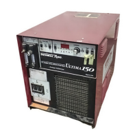
Detailed specifications for input power, output power, gas, coolant, weight, and dimensions.
Introduces service diagnostics for isolating faulty subassemblies.
Explains how to use indicator lights for troubleshooting.
Routine checks to verify system functionality using indicator lights.
Troubleshooting steps for AC indicator light issues.
Troubleshooting steps for temperature indicator light issues.
Troubleshooting steps for gas indicator light issues.
Troubleshooting steps for coolant indicator light issues.
Troubleshooting steps for pilot arc indicator light issues.
Troubleshooting steps for DC pilot indicator light issues.
Troubleshooting steps for A/V display status issues.
Procedures for replacing Logic/Display, Input, and Output PC Boards.
| Input Frequency | 50/60 Hz |
|---|---|
| Efficiency | 85% |
| Input Phase | Single-Phase |
| Output Current Range | 150 A |
| Output Voltage Range | 10 VDC |
| Duty Cycle | 60% |