Models 3940 and 3949 ________________________________________________________________Installation and Set-Up
2.12 1900140 IR CO2 Option
This section applies to units with the 1900140 IR CO
2
option only.
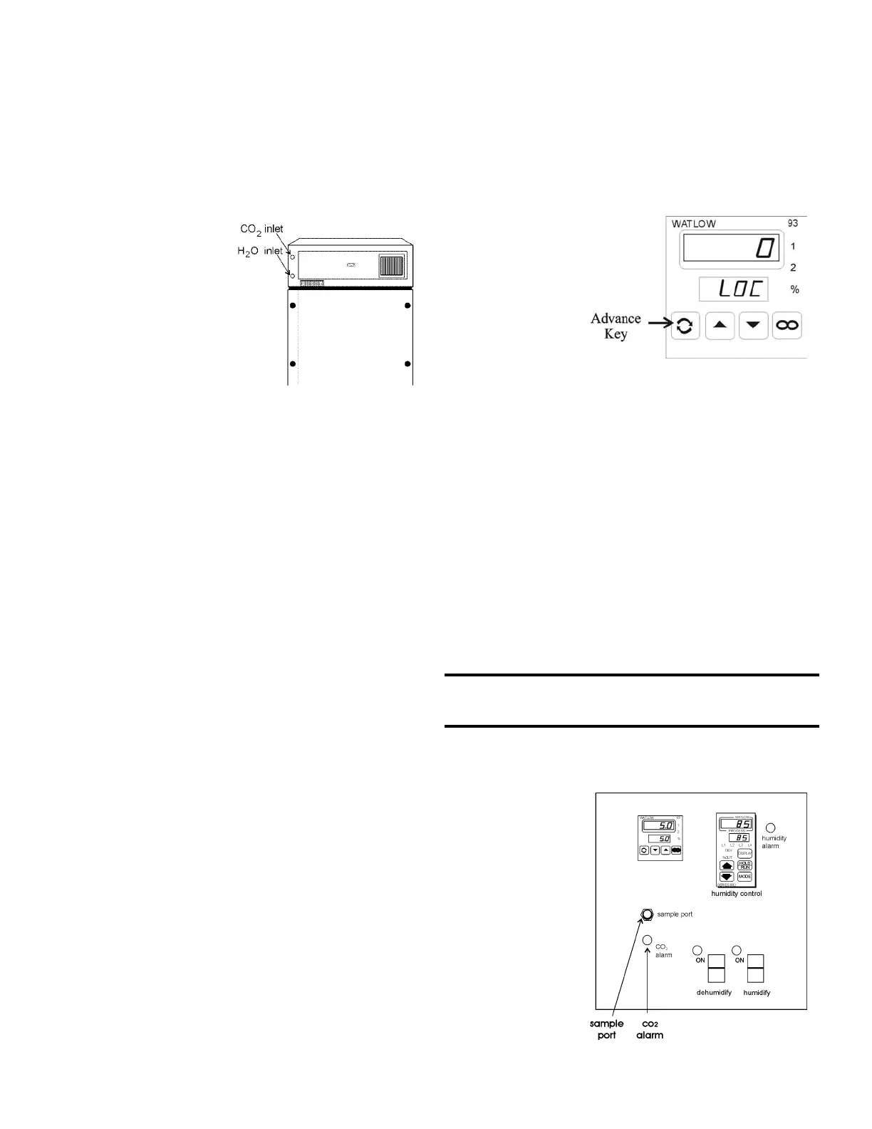
a. Connecting the CO
2 Source (Refer to Figure 2-3)
For the most economical use, the liquid CO
2 supply tanks
should be without siphon
tubes, so that only CO2 gas
enters the incubator injection
system. Two tanks may be
joined together with a mani-
fold to ensure a continuous
CO
2 supply.
Install a two-stage pres-
sure regulator, with indicating
gauges, at the supply cylinder
outlet. The high-pressure
gauge should have an indicat-
ing range of 0 to 2000 psig to
monitor tank pressure. The
low-pressure gauge should
have an indicating range of 0
to 30 psig to monitor input
pressure to the incubator injection system. A suitable two-stage
pressure regulator is available.
The CO
2 source must be regulated at a pressure level
between 5 and 10 psig. Higher pressure levels may damage the
CO2 control system. The user should determine the most eco-
nomical pressure level, between 5 and 10 psig appropriate for
the desired CO
2 percentage in the chamber. Use only sufficient
pressure to maintain recovery time after door openings.
To connect the CO
2 supply:
· Insert the copper tubing provided with the unit as far as it
will go into the nut of the CO2 connection.
· Turn the nut until it is finger tight.
· For reference, scribe the nut at the 6:00 position.
· While holding the fitting body steady with a wrench, tighten
the nut 1-1/4 turns until the mark is at the 9:00 position.
· Securely attach the CO
2 line to the open end of the copper
tubing.
· Check the tubing connection for leaks.
b. Setting the CO
2
Content
The Watlow 93 CO
2 controller's upper display shows
the actual CO2 content inside the chamber. The lower display
shows the CO2 setpoint.
Before setting the CO
2 Content, allow the chamber tempera-
ture and humidity to stabilize. Do not open door during the sta-
bilization period.
To set the CO
2 content, press the up or down triangles
on the Watlow 93 Controller.
c. CO
2 Controller Calibration
If it should become necessary to calibrate the CO
2 con-
troller, perform the following procedure. From the standard
operating display (setpoint in bottom display, actual CO
2 reading
in the upper display):
Enter the Setup Menu by pressing the t up-arrow and
6down-arrow keys
simultaneously on the
Watlow 93 controller for
three seconds. The
lower display shows the
Lock parameter, and the
upper display shows its
current level. Press
the6 down-arrow until
0 is displayed. Then,
use the Advance key to
move through the menus
until the "CAL" prompt appears.
Once at the "CAL" prompt, press thet up-arrow or 6
down-arrow to add or subtract the percentage of CO
2 to make
the display accurate. Press the Advance key until LOC appears.
Press the t up-arrow key to place "2" in the upper display.
Continue to press the Advance key until the setpoint display
appears.
d. CO
2
Control and Indicators
Sample Port (Refer to Figure 2-9)
The sample port is used for checking CO
2 percentage in the
incubator chamber by an independent test instrument (such as
with a Fyrite, or similar CO2 test instrument).
To prevent CO2 loss, the sample port must be capped when it is
not in use.
CO2 Alarm (Refer to Figure 2-9)
The CO2 alarm is factory set to activate when the
chamber CO
2 content
deviates ± 5%. When a
CO2 alarm occurs, the
CO
2 Alarm indicator on
the control panel lights
and the audible alarm
sounds.
The CO2
alarm high and low set-
points are established
through the Watlow 93
CO2 controller (ALO,
and AHI). Refer to the
configuration record
included at the end of
Section 2.
2 - 5
Figure 2-7
Figure 2-8
Figure 2-9