Do you have a question about the Thermo Scientific Ramsey Oretronic IV and is the answer not in the manual?
Key safety information for installation, operation, handling, transport, maintenance, and disposal.
Explains the distinction between CAUTION and WARNING messages used in the manual.
Lists essential safety precautions for installation, operation, and maintenance of the TMD IV.
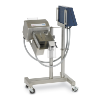
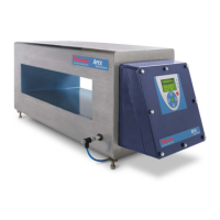
Describes the TMD IV's function in detecting tramp metal on conveyor belts and its capabilities.
Explains how the TMD IV operates using pulsed magnetic fields and secondary magnetic fields.
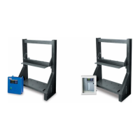
Explains how the coils are mounted on the support structure and their material.
Details the simplified operator interface, detection sensitivity, and software upgradeability.
Explains Modbus interface and synchronization of transmitter pulses for multiple detectors.
Lists system requirements and refers to engineering drawings for system configurations.
Outlines customer responsibilities for initial inspection and site preparation for the TMD IV.
Details crucial precautions and procedures to follow before connecting power or operating the unit.
Provides guidelines for proper coil support structure and coil mounting to ensure correct function.
Details the rating for output relays, including those with NO/NC contacts and NC only.
Highlights safety warnings related to high voltage and electrical shock hazards.
Guides users on inspecting packages and the unit for damage after unpacking.
Shows mounting dimensions and details for the fiberglass enclosure.
Shows mounting dimensions and details for the mild steel enclosure.
Step-by-step instructions for mounting the control unit enclosure, including conduit and hole placement.
Lists critical wiring conditions to ensure proper detector connection and safety.
Outlines following cable specifications from the Field Wiring Diagram for connections.
Configures core detection options like Sync Input, Bar/Rod Detect, and Clip Detect.
Sets up Speed Sensor, External Comms, Language, Units, Line Frequency, and Password Protection.
Details the process for calibrating the coarse and fine sensitivity of the TMD IV.
Continues clip sensitivity calibration and troubleshooting false trips from clips.
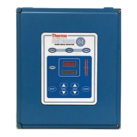
Introduces the operator interface, keys, indicators, and displays for TMD IV operation.
Explains the function of the indicator LEDs (NORMAL, ALARM, BYPASS, CALIB).
Details the membrane keypad, including the Reset key and soft-key functions.
Continues explaining keypad functions, including soft-keys and navigation.
Details Sync Input, Bar/Rod Detect, and Clip Detect options.
Explains Speed Sensor, External Comms, and Language options.
Covers Units and Line Frequency options.
Explains settings for Belt Speed, Material Code, and Operating Frequency.
Details settings for Marker Distance, Marker Duration, and Clip Length.
Covers Persistent Bypass and the View Menu.
Details procedures for routine maintenance of the TMD IV system.
Guides on determining the cause of detection or calibration problems.
Discusses common problems like false tripping or passing tramp undetected.
Details steps for balancing coils, including adjusting coil position.
Continues coil imbalance correction for single coil systems.
Troubleshoots mechanical and electrical noise sources affecting the TMD IV.
Continues noise troubleshooting and discusses adjusting operating frequency.
Adjusts sensitivity for high product noise by changing material code and sensitivity.
Adjusts clip detection and troubleshoots false trips from belt clips.
Tests for damage in coil or junction box by checking continuity.
Continues testing coil and junction box components.
Details Modbus message types supported and lists holding registers.
Provides details for service codes used to invoke functions and commands.
Explains the register containing the result of the last service invocation.
Describes the material code parameter controlling delay from excitation pulse to data acquisition.
Details the coarse sensitivity parameter controlling receive A/D gain.
Specifies the AC power line frequency for internal setup calculations.
Allows selection of the GUI language.
Gives the detection threshold indirectly via signal counts.
Details settings for Marker Distance and Marker Duration.
Counts detected tramp metal since alarm and total lifetime trips.
Indicates if a speed sensor is present for belt speed and position.
The measured belt speed based on sensor rate and meters per pulse.
Specifies the fine sensitivity value used in belt regions marked by a repair clip.
Specifies the length of belt repair regions for desensitization.
Specifies coarse sensitivity value for clip regions, modifying persistent register.
A status variable with bits for each alarm condition.
Indicates if the belt direction detection algorithm is reversed.
A flag to turn the Bar/Rod detection feature on and off.
Maximum bar length detectable by the bar/rod detection feature.
Specifies the sensitivity value for the bar/rod algorithm.
Specifies the baud rate used with the Modbus serial communication protocol.
Specifies the parity to be used for Modbus serial communication.
Enables synchronization of pulse generation between two detectors.
Enables a filter to reduce interference from welding noise.
Offers contact information for technical assistance and on-site service.
Details the recommended procedure for ordering replacement parts.
| Sensitivity | Adjustable |
|---|---|
| Aperture Size | Customizable |
| Weight | Varies by model |
| Construction | Heavy-duty steel |
| Control Unit | Microprocessor-based |
| Alarm Output | Relay contacts |
| Outputs | Relay outputs for alarm conditions |
| Housing | IP65 |
| Protection Rating | IP65 |