5.5 Setting the Door Heater Control
High voltage is present behind the control panel.
Servicing must be performed only by qualified
electrical service personnel.
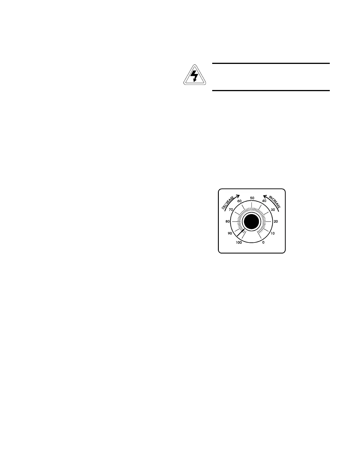
The infinite heater control is located in the right side of the
incubator top compartment behind the control panel door. The
heater varies the amount of door heat from no heat (zero) to full
heat (100) as indicated by the control dial face. If the knob is
turned past zero, a “click” will indicate that all power to the
door is shut off. If turned past 100, a similar “click” will indi-
cate that the heat is set at the maximum.
Initially, the units leave the factory with the dial set at 40.
If desired, the amount of heat can later be reduced until mois-
ture appears on the door, then the heat advanced. However, in
fluctuating ambient conditions, it is recommended that 40%
door heat be used.
8. Remove the nine 5/16” x 4” hex head bolts, lock wash-
ers, and two flat washers which secure the top assembly
to the cabinet. Note the washer arrangement on the
bolts.
9. Remove the black trim gasket located at the junction of
the top assembly and the main incubator section. The
ends of the gasket have been joined together at the rear
of the incubator.
Note: When raising the top section, note the orientation of the
gasket seal at the top opening of the incubator chamber. The
gasket must be correctly positioned when reinstalling the top on
the chamber.
10. Slowly lift the entire top assembly up and off the lower
chamber section while carefully guiding the capillaries
and sensing bulbs out of the chamber area. Place the top
assembly onto the carpenter’s horses or other support
arrangement.
11. Reinstall the top assembly by reversing the above proce-
dure. Exercise care particularly when:
• Placing and aligning the sealer gasket on the 1/2” flange
on top of the chamber when lowering the top in place.
• Routing the temperature and/or humidity sensors and
capillaries to prevent severely bending them.
• Mounting the temperature and/or humidity sensor bulbs
on the mounting brackets.
• Tightening the top mounting bolts alternately, to ensure a
balanced pressure on the gasket.
Model 3920 _______________________________________________________________________________Service
5 - 2
Figure 5-1