EasyManua.ls Logo

ThermoFisher Scientific iN10 User Manual

ThermoFisher Scientific iN10
61 pages
To Next Page IconTo Next Page
Page #1 background imageLoading...
Page #1 background image
Procedure: Installation
Title: Installing the iN10/iN10MX
Revision: 09
Procedure # Install-001
ECCN: EAR99
This document contains confidential or proprietary information of Thermo Fisher Scientific. Neither this
document nor the information therein is to be reproduced, distributed, used or disclosed, either in whole or
in part, except as specifically authorized by Thermo Fisher Scientific.
8/3/2020 Page 1 of 61
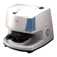
iN10/iN10MX
MX
Part number: 912A0604/912A0605/912A0804/912A0805
Part description: iN10/iN10MX Integrated Infrared Microscope
Tools required:
Scissor
Short handled medium Phillips screwdriver
Long handled medium Phillips screwdriver
Flat blade screwdriver
5/64” balldriver or L-wrench (array alignment)
Needle nose pliers (iZ10 interface installation)
Pliers (iZ10 installation)
3/16” L-wrench (iZ10 installation)
5/32” balldriver (iZ10 installation)
Laboratory grade powder-free gloves
ATR Crystal alignment procedure
Service test slide
100um Pinhole slide
Estimated time required: Approximately 4 -12 hours depending on
configuration.
Notes: N/A

Other manuals for ThermoFisher Scientific iN10

Question and Answer IconNeed help?

Do you have a question about the ThermoFisher Scientific iN10 and is the answer not in the manual?

ThermoFisher Scientific iN10 Specifications

General IconGeneral
BrandThermoFisher Scientific
ModeliN10
CategoryMicroscope
LanguageEnglish

Summary

Safety Precautions

Safety Risks

Identifies potential hazards and safety precautions during the procedure.

Software Configuration

Launch OMNIC Picta Software

Initiates the OMNIC Picta application and confirms microscope model.

Adjust Correction Factor

Modifies the flat-field correction setting in the OmnicSettings.ini file.

Configure Stage Control

Opens and configures the stage control screen for system operation.

Set Video Properties

Adjusts video capture properties, including gain, shutter, and white balance.

Optional Component Setup

Configure Mechanical Joystick

Enables the mechanical joystick within the diagnostic software.

Configure ATR Module

Sets the ATR module as installed in the system configuration.

System Verification and Alignment

Verify Aperture Centering

Checks and sets aperture centering parameters for optimal performance.

Verify Stage Operation

Checks the functionality and movement of the Z and condenser stages.

Interferometer Alignment

Aligns the interferometer for optimal transmission throughput.

Performance Testing

Run Transmission Performance Tests

Executes transmission performance tests, including TGS and MCT detectors.

Run Reflection Performance Tests

Sets up and runs performance tests in reflection mode.

Verify Imaging Detector

Checks and configures the imaging detector and related settings.

Verify Array Zoom Alignment

Aligns the array zoom aperture for accurate imaging.

ATR Module Setup

Select Reflection Mode for ATR

Sets the collection mode to Reflection for ATR measurements.

Adjust ATR Crystal Setscrew

Loosens the setscrew to allow adjustment of the ATR crystal.

Optimize ATR Focus for Throughput

Adjusts crystal rotation to maximize throughput and secures focus.

Identify ATR Crystal Footprint

Sets pressure and identifies the crystal footprint location.

iZ10 and ValPro Validation

Validate iZ10 Module

Validates the functionality of the iZ10 module, skipping if not applicable.

Complete ValPro Validation

Performs ValPro validation tests if the system was ordered with certification.

Finalizing and Documentation

Save System Parameters

Saves current system parameters for future restoration or backup.

Run Bench Status Report

Generates a report of factory calibration, configuration, and system status.

Complete IQ/OQ

Performs Installation Qualification and Operational Qualification if required.