Procedure: Installation
Title: iN10 Installation Checklist
Revision: 02
Procedure # Install-00
ECCN: EAR99
This document contains confidential or proprietary information of Thermo Fisher Scientific. Neither this
document nor the information therein is to be reproduced, distributed, used or disclosed, either in whole or
in part, except as specifically authorized by Thermo Fisher Scientific.
9/25/2012 Page 1 of 10
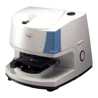
iN10/iN10MX
Part number: 912A0604/912A0605
Part description: iN10/in10MX Integrated Infrared Microscope
Functional description:
Problems associated with this assembly:
Tools required:
Scissor
Short handled medium Phillips screwdriver
Long handled medium Phillips screwdriver
Flat blade screwdriver
5/64” balldriver or L-wrench (array alignment)
Needle nose pliers (iZ10 interface installation)
Pliers (iZ10 installation)
3/16” L-wrench (iZ10 installation)
5/32” balldriver (iZ10 installation)
Laboratory grade powder-less gloves
ATR Crystal alignment procedure
Service test slide
100um Pinhole slide
Estimated time required: Approximately 4 -12 hours
depending on ValPro configuration.