Do you have a question about the Thermon TC 816 and is the answer not in the manual?
Overview of control methods including temperature maintenance and frost protection.
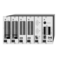
Power supply for 85-265 Vac, includes alarm contacts.
Handles independent operation, parameter storage, RS 485/Profibus comms.
8 circuit, 4 wire RTD PT 100 input module.
Determines 16 or 8 circuit setup for TC 816.
Modules for electronic relays (TOE) or mechanical contactors (TOM).
Module for load current monitoring or ZD TB1 blind plate.
Details the TCD 01 display, buttons (Up, Down, Enter, Acknowledge), and indicator lights.
Steps for starting up the TCD 01, including wiring and address setting.
Covers Number of First Circuit, Password, Language, Selftest Cycle Time, Baudrate.
Screen shown when password protection is active for set point changes.
Automatic search for connected TC 816 controllers on the RS 485 bus.
RESCAN, CONFIRM, SKIP options after bus search.
Shows status of heat tracing circuits (measured, setpoint, alarms).
Explains circuit numbers and TC 816 zone numbers for configuration.
Details columns like Controller/Zone Assignment, Measured, Setpoint.
Explains alarm codes for controller, limiter, and current lines.
How to acknowledge controller and current alarms using the 'Q' button.
Procedure to acknowledge high temperature alarms from a cable limiter.
Steps to modify circuit set points using display controls.
Steps to change specific parameters using the display controls.
Overview of zone parameters, user-alterable vs. supplier-configured.
Details user-configurable parameters (P01-P15) via the TCD 01.
Sets the low alarm threshold for temperature zones.
Sets the high alarm threshold for temperature zones.
Sets the deviation alarm threshold for temperature and current zones.
Sets the alarm delay in seconds to avoid spurious trips.
Programs digital inputs for MCB/RCD monitoring or operation mode input.
Configures operation mode: disable, manual, or automatic for each zone.
Sets manual power output (%) when OP MODE is set to manual operation.
Sets maximum controller power output (%) for PID control.
Monitors average power output (%) over the past automatic operation period.
Allows field tuning of temperature and current by adjusting offset.
Amount of passes through current transformer for low current measurement.
Sets start-up delay time for Frost Protection or ON/OFF control.
Spare parameters for future functional expansion.
Details supplier-configured parameters (P16-P29).
Sets communication address of the heat tracing cable temperature limiter zone.
Assigns the zone number of the heat tracing cable temperature limiter.
Selects the control mode: PID, APC, or ON/OFF.
Sets the proportional band (%) for PID control.
Sets the integration time (seconds) for PID control.
Sets the differential time (1/10 seconds) for PID control.
Sets the lowest ambient temperature for APC control.
Spare parameter for future functional expansion.
Determines the hysteresis for ON/OFF control.
Determines the cycle time (seconds) of the controller output.
Assigns the temperature controller zone number for the reference sensor.
Determines circuit number for temperature controller for Multiple Sensor MODE.
Determines the Multi Sensor mode (disabled, MIN, AV, MAX).
Spare parameter for future functional expansion.
| Brand | Thermon |
|---|---|
| Model | TC 816 |
| Category | Temperature Controller |
| Language | English |