Do you have a question about the Thetford Aspire and is the answer not in the manual?
Steps to remove control knobs, locking nuts, washers, and screws from the fascia.
Procedures to detach the fascia from its housing and disconnect ignition switch connectors.
Procedures including pan support removal and unscrewing various hob components like trim, caps, and studs.
Steps to remove the glass lid and loosen hinge screws for further access.
Lift and disconnect the hob pressing, including cables and earth connections, from the cooker.
Initial steps involve removing the cooker from housing and lifting the hob pressing.
Ensure earth straps are secure, then disconnect and replace the thermocouple spade fitting.
Identify black/copper thermocouples and trace them to disconnect spade fittings from the shut-off mechanism.
Use an 8mm spanner to remove the locking nut securing the thermocouple probe to the burner cup.
Verify electrode connection on the 12v generator and disconnect spade fittings.
Release hob burner electrodes by detaching the 'crocodile' clip and lifting the probe.
Remove the cooker from housing and detach the back plate and bracket screws for access.
Understand wiring configurations and ensure correct thermocouple-to-terminal correspondence for burner operation.
Detach spade fittings to remove the mechanism and handle the glass lid hinge pin carefully.
Remove the cooker, detach the rear galvanized plate, and release the spark generator clips.
Identify generator terminals for ignition, fans, and electrodes and disconnect spade fittings.
Detach galvanized plate screws holding the 12v fans.
Identify fan wiring, crimp positive and negative wires to bullet connectors.
Replace fans, ensuring correct polarity when connecting wires and orienting the fan label inwards.
Remove cooker housing, pressing, lid, trims, and unscrew rear box fasteners.
Retract flue diverter box and carefully manage wiring looms and grill box insulation.
Cut insulation tape and prize off starlock washers holding grill burner spigots.
Lower and remove grill burner tube after starlock washers are removed; use new washers on refitting.
Remove appliance from housing and detach the hob pressing to avoid damage.
Unscrew the bridging piece holding the burner valve and pull off the push-fit thermocouple.
Use a 10mm spanner to unscrew the nut holding the burner feed pipe to the valve.
Remove necessary screws and parts to gain access to the gas rail or manifold.
Use a PZ2 screwdriver to remove screws holding the thermostat mounting bracket.
Use a 13mm spanner for the oven feed pipe and a 17mm spanner for the gas rail connection.
Slacken 'P-clips' and pull the capillary tube and sensor probe through the oven cavity.
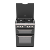
| Oven Type | Gas |
|---|---|
| Hob Type | Gas |
| Grill | Yes |
| Ignition type | Piezo |
| Gas type | Propane |
| Ignition | Electronic (12V) |