I nstallation
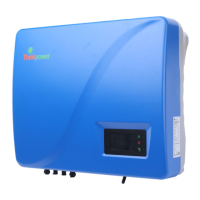
Fig.3-8
Fig.3-7
4) Fix the back board to the wall using the tapping screws tightly.
Fig.3-9
7) The installation is finished
13
I nstallation
12
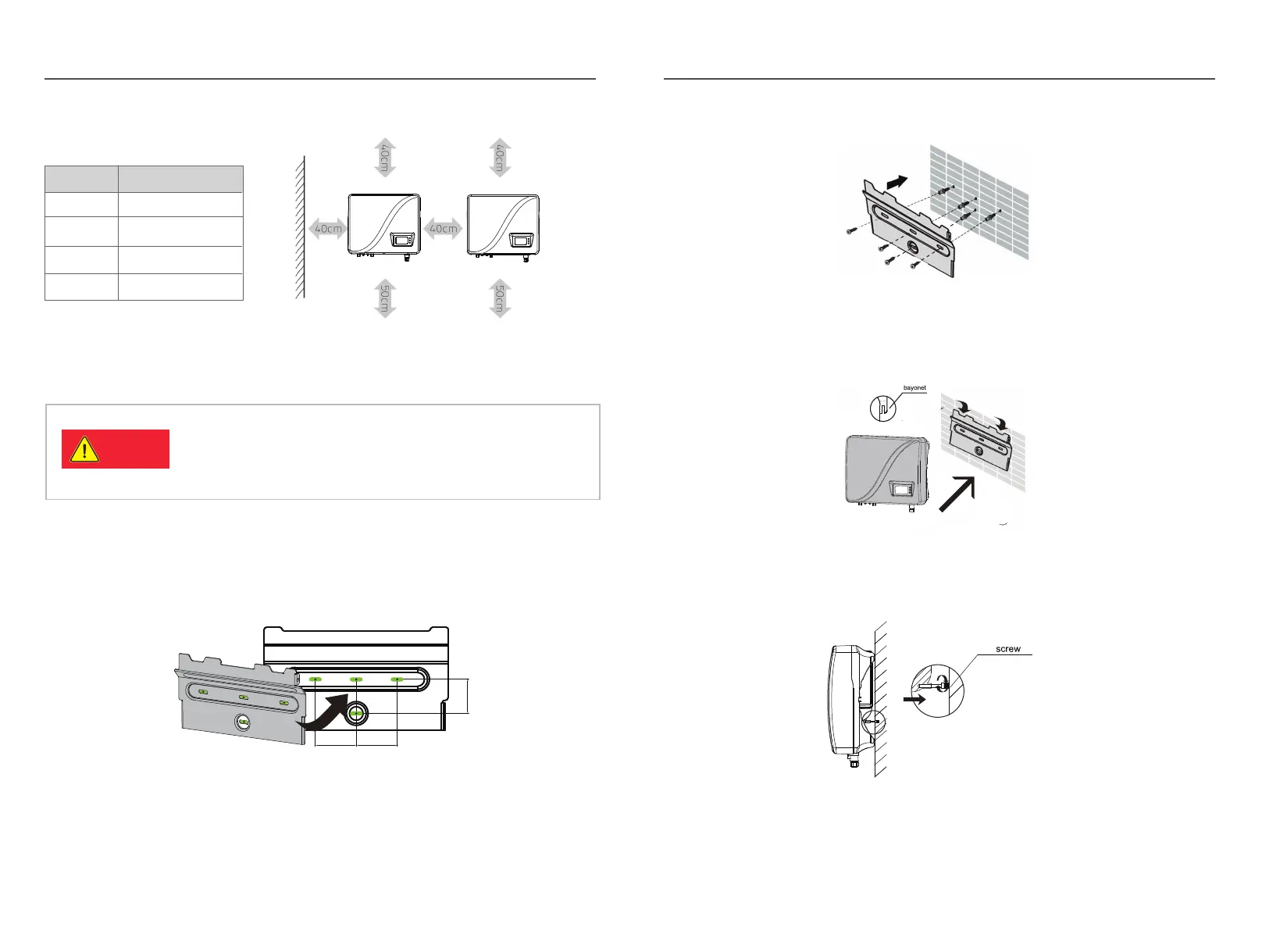
Tab.3-2: Effective spacing dimensions
Fig. 3-5
3.5 I nverter installation
3.5.1 I nstallation G uide
Fig. 3-6
Danger
1) Take out the back board and fix it to the wall; then peel the four green logos
on the back board and attach them to the wall through the hole. Thus the
installation holes are marked.
Please check that the open circuit voltage, short circuit
current and maximum power at S TC of the PV array are
within the capacity of the solar inverter.
The full load M PPT voltage range is within the
250V -480V .
2) Drill holes in the marked position as per the siz e of expansion screws.
3) I nsert the expansion tubes into the hole, knock the tubes into the hole and
make them level with the wall surface.
5) K eep the inverter tilts slight upward, and attach it to the wall bracket slightly
to the top of its final position, and then visually check if the inverter is correctly
installed on the bayonet.
6) After installing the inverter, adj ust the screw on the back of the box to
ensure that the inverter is parallel to the wall.
60mm
60mm
50mm