10
Orange pin exposed
Diaphragm protection
switch activated.
(Pump will not run.)
Diaphragm protection
switch not activated.
(Normal operation
mode.)
Common blade screw driver
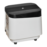
LP Housing LW Housing
(4) Housing screws (6) Housing screws
Applicable LP & LW Series Diaphragm Switch Deactivation Instruction:
Note: The LP & LW Series models contain dierent switches. Identify what type switch your pump has
by comparing the various photos and instructions below:
After positioning the diaphragm protection
switch to a vertical position with a common blade
screwdriver to deactivate switch, reassemble unit.
After positioning diaphragm protection switch
lever to “ON” position to deactivate switch,
reassemble unit.
Diaphragm protective switch
activated.
(Pump will not run.)
Diaphragm protective
switch activated.
(Pump will not run.)
Diaphragm protective switch
not activated.
(Normal operation mode.)
Diaphragm protective
switch not activated.
(Normal operation
mode.)
Disconnect power and remove housing screws and housing.
After positioning diaphragm protection
switch lever to “ON” position to deactivate
switch, reassemble unit.
Diaphragm protective
switch activated.
(Pump will not run.)
Diaphragm protective
switch not activated.
(Normal operation mode.)
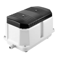
Ensure to install the noise absorbing net to cover
the connection terminal by its tail end.
LW Noise Absorbing Net Position Instruction:
Pay attention to the direction in which the noise
absorbing net for LW model is installed.
Use a common blade screwdriver to push lower
portion of black switch lever over orange pin so
that the orange pin is no longer exposed.
After positioning diaphragm
protection switch to proper position to
deactivate switch, reassemble unit.