Temperature Controlled, Laser Diode Mount
1981-D03, Rev N June 26, 2015
Figure 3 LD and PD Orientation
5. Replace the laser mounting flange and the cover. Install both screws through the
mounting flange and loosely into the cold plate, then carefully tighten each screw
a little bit at a time until the flange is just snug. Do not over tighten either screw
– the flange will sit slightly above the cold plate. Reinstall the cover using the
four 2-56 cap head screws provided.
Note: The four sockets comprising the laser diode connector are through hole type
sockets with a blind clearance of 0.75" measured from the front face of the copper
cold plate. It is not necessary to trim the laser diode leads prior to mounting into
this connector unless they are longer than 0.75".
Note: The laser connector is located close enough to the front face of the copper
cold plate to allow easy installation of short leaded lasers. The clearance area
around the LD and PD sockets is sufficient to prevent the pins from contacting the
cold plate.
Special Note for G Style Configuration Laser Diodes
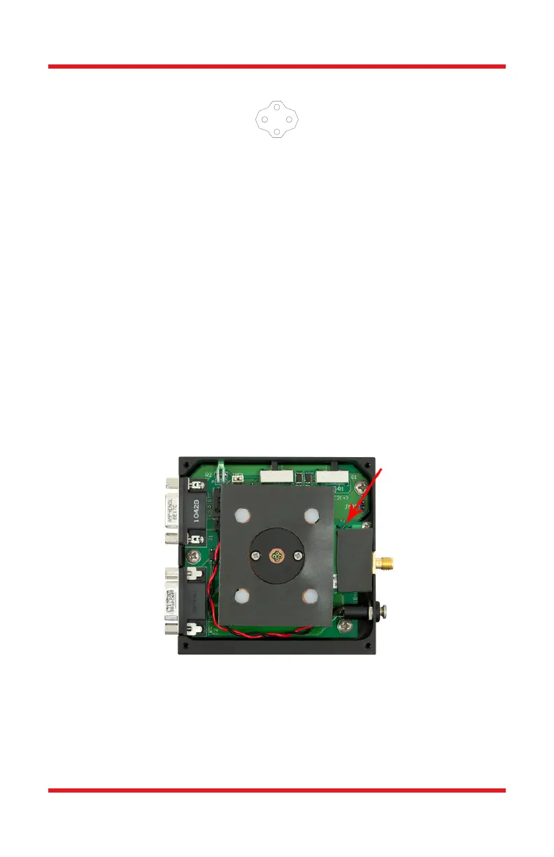
Figure 4 TCLDM9 Internal Circuitry Showing Jumper 14
In order to drive a style G laser diode, the PD pin in the mount must be grounded. To
ground the PD pin, remove the front cover to the TCLDM9 mount. Locate jumper J4
on the right-hand side of the mount. A photo of the TCLDM9 internal circuitry is
shown in Figure 4, and jumper J4 is marked with a red arrow. Short J4 pin 3 (ground,
right pin) to J4 pin 2 (photodiode, middle pin). Grounding the photodiode pin will
G
G
PD
LD
 Loading...