Temperature Controlled, Laser Diode Mount Chapter 4: Setup
Page 6 Rev N, June 26, 2015
Chapter 4 Setup
4.1. Laser Installation
To install the laser diode, complete the following steps:
1. Unpack the laser mount and remove the four 2-56 socket head screws from the
front cover using a 5/64" hex driver.
2. Remove the two Philips head 2-56 screws from the laser-mounting flange and
remove the flange.
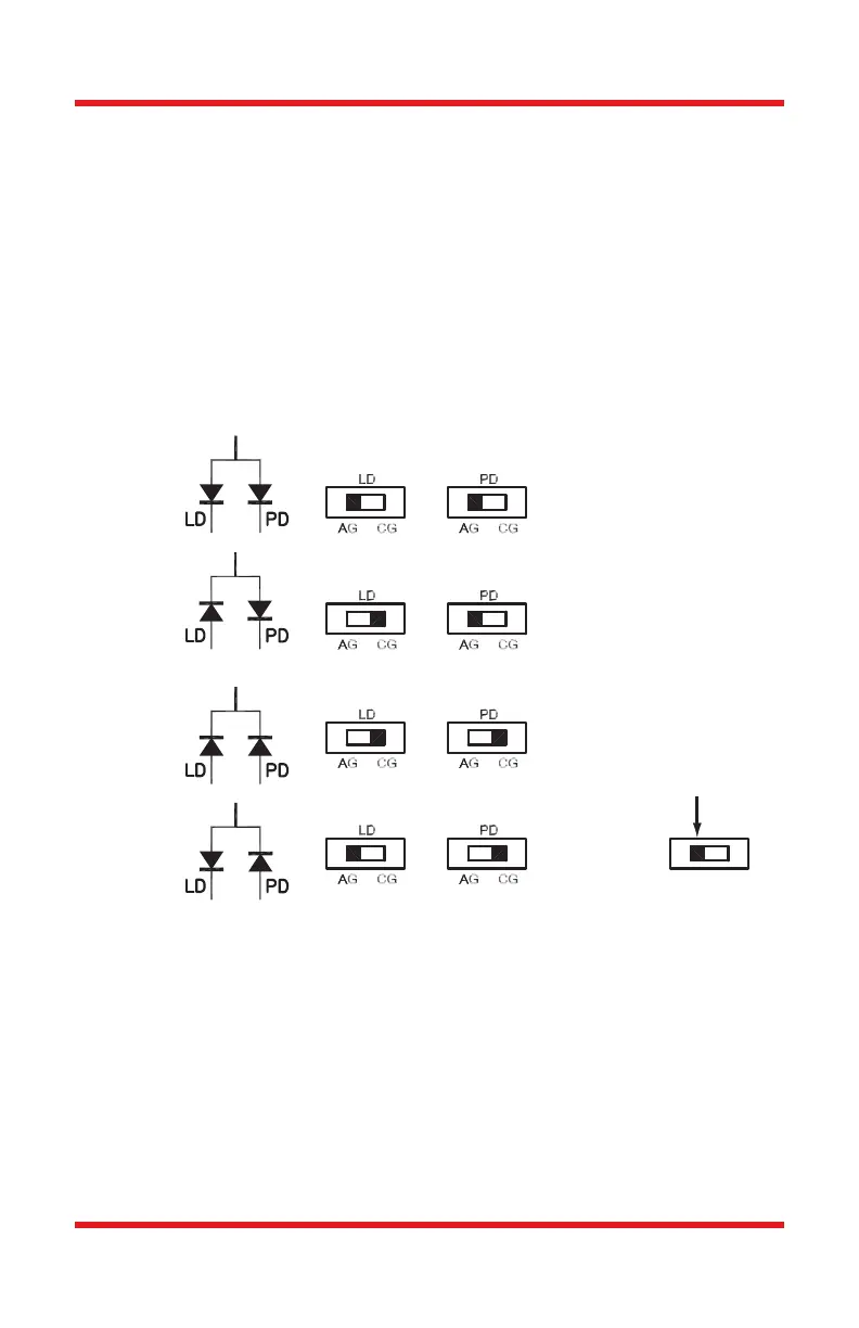
3. Determine the laser pin configuration from the laser diode manufacturer’s data
sheets and set the LD (Laser Diode) and PD (Photodiode) switches located on
the top of the unit according to the figure below.
Figure 2 Polarity Switch Settings
4. Most laser diodes are three pins with the case tied to one of the laser pins and
also to one of the photodiode pins. The other laser and photodiode pin will be
isolated from the case. The TCLDM9 was designed to operate the laser case at
ground potential therefore this common pin will be inserted into either the 12
o’clock or the 6 o’clock position of the laser connector. Locate the isolated laser
pin and insert it in the 3 o’clock position. The isolated photodiode should now
be in the 9 o’clock position. Refer to the figure below.
Position
Switch
 Loading...