This document serves as the Installation, Operation & Maintenance Manual for AIR-COOLED MODULAR CHILLERS, specifically covering FCA/TCA 201-301 EC/EH and FCA/TCA 201-301 NC/NH models. It provides comprehensive guidelines for the safe and efficient handling, setup, operation, and upkeep of these chiller units.
Function Description:
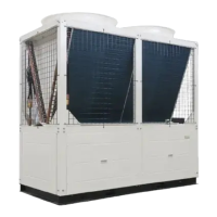
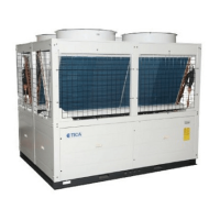
The air-cooled modular chiller is designed for cooling and heating applications, providing chilled water for various systems such as Fan Coil Units (FCU) or Air Handling Units (AHU). Its modular design allows for flexible installation and scalability, catering to different capacity requirements. The chiller operates by circulating refrigerant through a closed loop, transferring heat from the water system to the ambient air via condenser coils. Key components include compressors, fan motors, heat exchangers (evaporator and condenser), and a sophisticated control module that manages and monitors the system's performance. The system can operate in both individual and group control modes, making it suitable for a wide range of commercial and industrial applications.
Important Technical Specifications:
- Models Covered: FCA/TCA 201-301 EC/EH and FCA/TCA 201-301 NC/NH.
- Dimensions (in mm):
- FCA 201 / 301 EC / EH:
- FCA201 EC/EH: A=1030, B=515. Overall dimensions include a height of 2063, width of 2206, and depth of 779.
- FCA301 EC/EH: A=1073, B=536.5.
- FCA 201 / 301 NC / NH: Overall dimensions include a height of 1940, width of 1028, and depth of 1120 (or 1320 for a different view).
- Water Pipe Size: DN40 for each module.
- Chilled Water Supply and Return Pipe Diameters (DN in mm) based on Cooling/Heating Capacity (kW):
- 50 kW: 50 mm
- 120 kW: 80 mm
- 230 kW: 100 mm
- 350 kW: 125 mm
- 465 kW: 150 mm
- 580 kW: 170 mm
- 700 kW: 200 mm
- Electrical Specifications:
- Power Supply: 380V/3N~/50Hz.
- Voltage Tolerance: ±10% of rated voltage.
- Phase Imbalance: Not greater than 2%.
- Communication Bus Cable: Shielded Twisted Pair cable, no less than 0.25mm² in size, with consistent polarity for A & B wires.
- Current Ratings (Total Running Current A / Main Power Supply Cable Size mm²):
- FCA - EC/EH:
- FCA201: 45.0 A / 16 mm²
- FCA301: 65.0 A / 25 mm²
- FCA202: 85.0 A / 25 mm²
- FCA201+301: 105.0 A / 35 mm²
- FCA203: 125.0 A / 35 mm²
- FCA202+301: 145.0 A / 50 mm²
- FCA204: 165.0 A / 50 mm²
- FCA203+301: 185.0 A / 70 mm²
- FCA205: 205.0 A / 70 mm²
- FCA206: 245.0 A / 95 mm²
- FCA207: 285.0 A / 120 mm²
- FCA208: 325.0 A / 150 mm²
- FCA209: 365.0 A / 185 mm²
- FCA210: 405.0 A / 240 mm²
- FCA211: 445.0 A / 300 mm²
- FCA212: 485.0 A / 300 mm²
- FCA209+303: 545.0 A / 400 mm²
- FCA206+306: 605.0 A / 400 mm²
- FCA203+309: 665.0 A / 400 mm²
- FCA312: 725.0 A / 400 mm²
- FCA - NC/NH:
- FCA201: 45.0 A / 16 mm²
- FCA301: 63.8 A / 20 mm²
- FCA202: 90.0 A / 35 mm²
- FCA201+301: 108.8 A / 35 mm²
- FCA203: 135.0 A / 50 mm²
- FCA202+301: 153.8 A / 70 mm²
- FCA204: 180.0 A / 70 mm²
- FCA203+301: 198.8 A / 95 mm²
- FCA205: 225.0 A / 120 mm²
- FCA206: 270.0 A / 150 mm²
- FCA207: 315.0 A / 185 mm²
- FCA208: 360.0 A / 240 mm²
- FCA209: 405.0 A / 240 mm²
- FCA210: 450.0 A / 300 mm²
- FCA211: 495.0 A / 300 mm²
- FCA212: 540.0 A / 400 mm²
- FCA209+303: 596.4 A / 400 mm²
- FCA206+306: 652.8 A / 400 mm²
- FCA203+309: 709.2 A / 400 mm²
- FCA312: 765.6 A / 430 mm²
- Power Supply Cable for Each Module (mm²):
- FCA201: R,S,T=16, N=10, Earth=10.
- FCA301: R,S,T=25, N=10, Earth=10.
- FCA201 (NC/NH): R,S,T=16, N=10, Earth=10.
- FCA301 (NC/NH): R,S,T=20, N=10, Earth=10.
- Water System Volume: Minimum volume per module (V) calculated as V = 14.17 * Ts * ( (TD/H1) + (TD/H2) ), where Ts is time interval (recommended 10 minutes), TD is temperature interval (recommended 2 °C), H1 is chiller capacity per step (FCA201=33kW, FCA301=50kW), and H2 is minimum load required by the system.
- Expansion Tank Volume: (0.03~0.034) * VC (System Volume).
- Water Pressure Test: Greater than 1.25 times working pressure, not less than 0.6MPa. Pressure drop less than 0.02MPa after 5 minutes indicates leak-free.
Usage Features:
- Modular Design: Allows for flexible installation and expansion based on cooling/heating demands. Each module has a pre-set address via DIP switch for proper placement.
- Advanced Control Module:
- Multi-color backlight LCD display: Provides clear visibility of system status.
- Individual or modular control: Supports flexible operation modes.
- Real-time clock and 7-day ON/OFF timer: Enables scheduled operation for energy efficiency.
- Temperature display: Shows leaving/entering water temperature, outdoor ambient temperature, module entering/leaving water temperature, and condenser temperature.
- Parameter settings: Allows users to adjust various control parameters.
- Manual defrost: User-initiated defrost function.
- Last state memory: Retains previous settings after power interruptions.
- Key lock function: Prevents unauthorized changes to settings.
- Error codes display: Provides diagnostic information for troubleshooting.
- Safety Protections: Equipped with safety devices for optimum operation. Malfunctions trigger alarms and disable corresponding protection features.
- Remote ON/OFF: System can be controlled remotely via contact closure.
- External Alarm/Interlock: Integrates with external alarm systems and interlocks for enhanced safety and control.
- Remote Cool/Heat (Mode HA): External interlock controls cool/heat mode, while remote ON/OFF controls system power.
Maintenance Features:
- Scheduled Inspection: Recommended to prolong lifespan and reduce downtime.
- Condenser Coil Inspection: Regularly check for dirt and debris; clean as necessary.
- Piping Components: Inspect all piping, clean strainers, and replace if necessary.
- Wiring Connections: Check and tighten all wiring connections.
- Water Drainage: Completely drain water if the unit is not operating for extended periods.
- Refrigerant System Leak Test: Perform if pressure drop occurs.
- Evaporator Cleaning: Chemical cleaning is recommended as mechanical cleaning is not possible. This must be done by authorized dealers using specific chemical additives and procedures, or by professional water treatment personnel.
- Troubleshooting Guide: The manual includes a comprehensive table of faults, possible causes, and recommended settings for various error codes, aiding in quick diagnosis and resolution of operational problems.
- Reset Functions: Auto-reset for certain alarms (recovers after 5 minutes), manual reset for others (requires pressing and holding key), and system restart for water flow and power supply errors.