This document is an installation and operation manual for the TICA MINI VRF (CHR/CSREA series) air conditioning system. It provides comprehensive information for installers and users, covering safety precautions, installation procedures, technical specifications, and operational guidelines.
Function Description
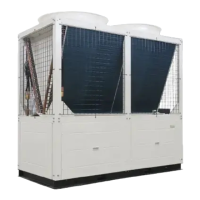
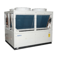
The TICA MINI VRF system is a household inverter VRF air conditioning unit designed for cooling and heating applications. It utilizes variable refrigerant flow technology to provide efficient and flexible climate control for multiple indoor units (IDUs) connected to a single outdoor unit (ODU). The system is capable of simultaneously providing cooling or heating to different zones, depending on the specific model and configuration.
Important Technical Specifications
ODU Cooling Capacity
The ODU models are available with various cooling capacities, ranging from 8.0 kW to 33.5 kW. The specific models and their corresponding capacities are:
- TIMS080CHR: 8.0 kW
- TIMS100CHR: 10.0 kW
- TIMS112CHR: 11.2 kW
- TIMS125CHR: 12.5 kW
- TIMS140CHR: 14.0 kW
- TIMS160CHR: 16.0 kW
- TIMS180CSREA: 18.0 kW
- TIMS200CSREA: 20.0 kW
- TIMS224CSREA: 22.4 kW
- TIMS252CSREA: 25.2 kW
- TIMS285CSREA: 28.5 kW
- TIMS335CSREA: 33.5 kW
Maximum Number of IDUs
The maximum number of indoor units that can be connected to an ODU varies by model:
- 8.0 kW: 4 IDUs
- 10.0 kW: 5 IDUs
- 11.2 kW: 5 IDUs
- 12.5 kW: 6 IDUs
- 14.0 kW: 7 IDUs
- 16.0 kW: 8 IDUs
- 18.0 kW: 9 IDUs
- 20.0 kW: 10 IDUs
- 22.4 kW: 11 IDUs
- 25.2 kW: 13 IDUs
- 28.5 kW: 15 IDUs
- 33.5 kW: 16 IDUs
Power Supply
The suffix 'A' indicates a 3N-380V 50Hz power supply. For specific ODU models, the power supply and voltage range are detailed in the wiring specifications:
- Single phase (220V/50Hz):
- 8.0 kW to 16.0 kW: 198/242 V
- Three phase (380V/50Hz):
- 18.0 kW to 33.5 kW: 342/418 V
Refrigerant Piping Limits
The manual specifies various limits for refrigerant piping to ensure optimal system performance:
- H1 (ODU at upper position): ≤ 20 m
- H1 (ODU at lower position): ≤ 15 m
- H2 (ODU at same level): ≤ 8 m
- L1+L2+L3 (longest piping distance from first branch pipe): ≤ 20 m (equivalent)
- LM (total actual length of liquid and gaseous side): ≤ 50 m (actual)
- LM (total equivalent length of liquid and gaseous side): ≤ 60 m (actual), ≤ 70 m (equivalent)
- L3 (longest piping distance from first branch pipe to furthest IDU): ≤ 15 m (equivalent)
- Total length (all pipes): ≤ 100 m (actual)
Pipe Diameters
The diameters of the main pipes in the figure are chosen based on the ODU capacity and the equivalent length of the liquid and gas pipes. For example:
- 8.0 kW: Liquid pipe 9.52 mm, Gas pipe 15.88 mm
- 14.0 kW: Liquid pipe 9.52 mm, Gas pipe 19.05 mm
- 22.4 kW: Liquid pipe 12.7 mm, Gas pipe 19.05 mm
- 33.5 kW: Liquid pipe 12.7 mm, Gas pipe 25.4 mm
Branch Pipes
The piping between branch pipes and IDUs should have the same sizes as the IDU piping. The total capacity of connected IDUs determines the liquid and air pipe specifications for branch pipes. For example:
- X ≤ 16.8: Liquid pipe φ 9.52, Air pipe φ 15.88
- 16.8 ≤ X < 22.5: Liquid pipe φ 9.52, Air pipe φ 19.05
- 22.5 ≤ X < 33.0: Liquid pipe φ 12.7, Air pipe φ 22.2
- 33.0 ≤ X: Liquid pipe φ 12.7, Air pipe φ 25.4
Branch pipes can be vertically or horizontally installed, with the angle between horizontally installed pipes being ±15°. The straight pipe distance between two adjacent branch pipes should not be less than 1000 mm.
Equivalent Length of Elbows
The equivalent length of an elbow is used to calculate pressure losses in the piping system.
- φ 9.52: 0.18 m
- φ 12.7: 0.2 m
- φ 15.88: 0.25 m
- φ 19.05: 0.35 m
- φ 22.23: 0.4 m
- φ 25.4: 0.45 m
- φ 28.6: 0.5 m
- φ 31.8: 0.55 m
Usage Features
Installation Space Requirements
- ODU Installation Position: The ODU should be installed on a roof or a well-ventilated place, ensuring sufficient strength to bear the unit weight and vibration. The roof must be strong enough and water-proof.
- Unsuitable Places: Avoid installing the ODU in places where acid or alkaline substances, corrosive gases (e.g., sulfur dioxide and hydrogen sulfide), flammable gases, or volatile combustibles may be produced.
- Clearances: Specific clearances are required around the ODU for proper air circulation and maintenance. For example, a minimum of 500 mm clearance is needed on one side, and 2000 mm on the other for air inlet/outlet. For maintenance, a minimum of 600 mm is required.
Handling and Placement
- Fragile Unit: The ODU is fragile and should be handled with care. The degree of inclination during handling should not exceed 30°.
- Heat Exchanger Fins: Protect heat exchanger fins from damage during handling and installation.
- Packaging: Dispose of packaging bags and prevent children from playing with them.
- Lifting: Use a forklift to handle the ODU, ensuring the fork is inserted into the pocket at the bottom and preventing damage. Use a crane with a tightened hoisting rope, ensuring the unit weight is evenly distributed during hoisting.
- Hoisting Ropes: Use two hoisting ropes at least 8 m long and 20 mm in diameter.
- Wooden Framework: Remove the wooden framework carefully to avoid damaging the unit body.
- Foundation: Ensure the ODU is placed firmly on a level surface to prevent vibration and noise. Use a base larger than the width of the ODU's support legs (66 mm) to support the unit. Shock-absorbing pads should cover the entire bearing surface of the base. The unit base should be at least 200 mm higher than the ground.
- Condensate Water: The base should be drained to ensure that condensate water generated during operation can flow out.
- Anchor Bolts: Use anchor bolts, nuts, and pads to fasten the ODU tightly to the base. Shock-absorbing pads should cover the entire bottom of the unit, and the pad thickness should be greater than or equal to 20 mm.
- Corrosion Protection: For anti-corrosive models, use rubber pads. If the nut joints get loose, the unit will not be corrosion-proof.
Refrigerant Piping
- Cleanliness: Ensure clean piping free from dust, moisture, or any other substances.
- Installation: Store all pipelines needed for installation indoors, and keep two ends of pipelines sealed until welding.
- Wall Penetration: Pass copper pipes into the holes at the wall and seal the holes to prevent dirt from coming in.
- Rainy Days: Avoid ODU piping work on rainy days to prevent moisture and dirt from entering the pipelines.
- Bending: Reduce bent piping and use bends with larger radii.
- Completion: When connecting refrigerant piping, the stop valve of the ODU should be closed completely. Air tightness test, vacuumizing, and refrigerant leakage test must be performed after refrigerant piping between ODU and IDU is done.
Air Tightness Test, Vacuumizing, and Supplementing Refrigerant
- Tools: Use a vacuum pump, pressure gauge, and compound pressure gauge designed for R410A refrigerant.
- Air Tightness Test: After piping work, conduct an air tightness test for IDU and piping. Do not use flammable gas or air (oxygen) as pressurized gas, as fire or explosion may occur; use nitrogen only.
- Steps:
- Increase pressure by 0.3 MPa for three minutes, and check for leakage.
- Increase pressure to 1.5 MPa for three minutes, and check for minor leakage points.
- Increase pressure to 4.0 MPa for 24 hours, and check for micro leakage points.
- Important: Use nitrogen in air tightness test instead of oxygen, flammable and toxic gas, or water. Use R410A dedicated pressure gauge with measuring range above 4.5 MPa. Connect high pressure pipe and low pressure pipe and increase pressure to them at the same time, without connecting to ODU. After passing air tightness test, if not used immediately, release system pressure to 0.2-0.3 MPa and then seal it.
- Vacuumizing:
- Steps:
- Use a vacuum pump with volume above 4 L/s. The vacuum degree must support -755 mmHg or lower.
- To prevent lubricating oil from flowing in the reverse direction to refrigerant system, use a vacuum pump with electronic one-way valve.
- Supplementing Refrigerant:
- Pre-delivery: ODUs are filled with a certain amount of refrigerant. The installer is responsible for adding refrigerant according to the actual length of refrigerant piping at the installation site.
- Steps:
- Close the compound pressure gauge, replace the vacuum pump with a filling tank connected with a charging pipe. Make sure the air is drained completely, and connect the joints of filling tanks and put the tank mouth down on the platform scale.
- Set the quantity to be filled at the electronic scale, and successively open the valve of the filling tank and valve of compound pressure gauge to fill the system with refrigerant. When reaching the limits, immediately close the valve of the filling tank and disconnect connection pipes.
- Caution: For refrigerant tank with siphon, the tank needs not to be put upside down. If using an R410A filling tank without siphon, make sure the tank is put upside down.
- Calculation: Supplemented refrigerant quantity = Σ liquid pipe length at various diameters × supplemented refrigerant quantity per meter × 0.8.
Electrical Control Installation
- Wiring Cautions:
- Power Wire: Use copper wire as power wire and do not make it too tight.
- Power Supply: All IDUs and ODUs of the same system must be supplied with power simultaneously.
- Distribution Box: The distribution box should be provided with a set of electric leakage protection device and a switch for each module.
- Grounding: Make sure all the earth lines of the unit are connected to ground securely. Do not connect earth lines to lightning devices, telephone lines, gas pipes, or tap water pipes. Improper grounding may cause electrical shock or fire.
- Communication Line Wiring:
- TIMS Series: TIMS series household inverter VRF air conditioning unit has both high voltage (power) line and control (communication) line. Do not connect power line to the connecting terminal of communication cables.
- Length: The total length of the communication line is less than 1000 m.
- Shielding Layer: The shielding layer of the communication line must be connected to earth lines of each module and IDUs securely.
- Power Plug: Do not remove the power plug with power on, lest the communication chips would be damaged.
- High Voltage Signal: To prevent high voltage signal from disturbing control signal, shielded twisted pair must be used.
- Polarity: Try to select shielded twisted pair with dense shielding layers and smaller lay. Control signal has two polarities, A and B, and different polarities cannot be connected, otherwise communication failures may be caused.
- Parallel Lines: When the power line is parallel with the communication line, they shall be covered by respective conduits and kept at some distance away.
ODU Control Panel
The ODU control panel features a digital display and DIP switches for setting parameters.
- Code Settings:
- '0' and '1': '0' for the status above, and '1' when dialed to the "ON" position.
- ODU Address: Description on ODU address setting is based on the specific situation after installation is completed.
- Reset: The unit must be powered on again after the DIP switch is reset.
- Normal Indication: '0' indicates normal, while '1' indicates silent mode for No. 4 switch.
- SW2 (DIP switch of ODU capacity): Used to set the cooling capacity of the ODU. The ODU capacity code has been set properly before delivery; check whether the setting is right.
- S1 (Model Setting): Used to set the model type (Single phase or Three phase) and other related parameters.
- S3 (DIP switch of ODU capacity): Similar to SW2, used to set the ODU capacity.
- Parameter Setting (MEU1, MEU2, MEU3):
- MEU1: Set parameters like centralized control address (SP01), baud rate (SP02), silent mode (SP03), manual power on/off (SP09), manual address clearing (SP10), and manual oil return (SP11).
- MEU2: Display parameters like system parameters (00-38) and current fault code (E*** EC**).
- MEU3: Set features like forced defrosting and open valve.
- Navigation: Use KEY1 to cyclically display MEU1/MEU2/MEU3. Use KEY4 to confirm your choice and enter the next level. Use KEY2/KEY3 to scroll up and down, and KEY4 to confirm to enter the next level of menu.
Maintenance Features
Safety Precautions
- Manual Review: Read the manual carefully before installation and use.
- Qualified Personnel: Installation should be left to a licensed professional. Users shall not install, repair, or displace the air conditioning unit by themselves.
- Power Circuit: Be sure to use a dedicated power circuit. Make sure the supply voltage fluctuates within ±10% of rated voltage. Power supply should be separate from welding transformer because the latter may cause large voltage fluctuation.
- Local and National Codes: Get a licensed electrician to install the unit according to national and local power standard, and to check whether line capacity meets requirements and whether power lines are loose or damaged.
- Electrical Control Schematic: Refer to the "Electrical control schematic diagram" attached to the backside of the cover plate of ODU control box.
- Cover Plate: The cover plate for the control box must be fastened to prevent incoming of dust and water. The electrical parts must be waterproof and away from water sources, otherwise electric shock or fire may be caused.
- Piping Leakage: After installation, be sure to make an air tightness check whether there is pipeline leakage.
- ODU Connection: A long time, ODU power must be connected 24 hours before use. Otherwise, the compressor may be burnt (make sure the air conditioner is in standby mode at the seasons they are needed most).
- Panel Removal: Do not turn on the air conditioner when the panel or protection screen is removed. The moving parts inside the air conditioner may hurt people or other objects.
- Refrigerant Piping: Do not touch refrigerant pipeline during operation or just at the end of operation.
- Pipeline Leakage: The pipeline of the air conditioner may be very hot or cold during its operation, which may lead to scald or frostbite.
- Power Off: Do not turn off power immediately after the unit stops. Wait at least for five minutes, otherwise water leakage may occur.
- General Power Supply: Cut off general power supply during seasons the air conditioners are not used, so as to prolong the service life and save energy.
- System Compatibility: All the IDUs and ODUs of the same system must be supplied with power simultaneously.
Precautions for Using R410A Refrigerant
- Supplement Refrigerant: Please supplement refrigerant system with liquid refrigerant. In the case of gaseous refrigerant, composition of refrigerant in the system may change.
- Mixing Refrigerants: Do not mix into other refrigerants.
- Tools: Do not use the following tools ever used for common refrigerants (such as R22): pipeline, pressure test devices, filling hoses, leakage detection devices, refrigerant filling base, and refrigerant recovery devices.
- Vacuum Pump: Make sure to use a vacuum pump dedicated for R410A series.
Precautions When Breaking Through the Knockout
- Unit Shell: Do not damage the unit shell when trying to break through the knockout.
- Hole Trimming: Ensure the hole to be trimmed after being broke through with a hammer, and protect it from corrosion by painting.
- Wiring Protection: When passing the wire through the knockout, put a grommet in the hole or wrap wires with adhesive tape for protection.
Precautions at Trial Operation
- First Use: When the system is powered on for the first time or after being left unused for a long time, ODU must be connected 24 hours before use. Otherwise, the compressor may be burnt.