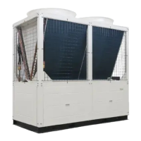
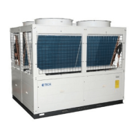
This document is an Installation & Operation Manual for a Modular Air-Cooled Chiller (Heat Pump) manufactured by TICA.
Function Description
The TICA Modular Air-Cooled Chiller (Heat Pump) is an air conditioning unit designed for a wide range of industrial and civil construction projects, including hotels, shopping malls, office buildings, entertainment centers, theaters, stadiums, plants, hospitals, and high-grade apartments. Its modular design allows for flexible installation and control, making it suitable for Central Business Districts (CBDs) and water-stressed regions as it does not require dedicated equipment rooms or cooling towers.
The unit operates using an innovative modular design, where the entire system comprises one or more modules. Each module contains two or four independent cooling systems, and their electric controllers operate independently while being connected via communication cables to form a control network.
Key features include:
- High efficiency, energy saving, and reliable performance: Utilizes efficient scroll compressors and world-renowned cooling components.
- High-precision EXVs for throttling: Employs Electronic Expansion Valves (EXVs) for fine and adaptive control, optimizing refrigerant and compressor matching to ensure efficient operation and system pressure management.
- Support for connection to building automation systems: Equipped with RS485 interfaces for centralized building control system integration, enabling building automation.
- Convenient installation: Compact design allows installation on roofs, spacious balconies, or other open spaces, reducing installation space requirements. It eliminates the need for cooling towers, cooling water pumps, boilers, and extensive piping.
- Intelligent defrosting: Automatically determines optimal defrosting time based on ambient temperature and operation parameters to prevent frost buildup and frequent defrosting. Intelligent defrosting and anti-freezing operations are controlled automatically.
- Multi-protection design: Features hierarchical startup to reduce impact on the power grid. Includes protections such as compressor overload, water shortage, system overpressure, system under-pressure, compressor exhaust over-temperature, frequent unit startup, external interlock, water outlet under-temperature, and automatic winter anti-freezing.
- Microcomputer control system: Centralized control for multiple modular units (up to 16 units per controller). Functions include timed power-on/off (with weekend and holiday settings), automatic fault judgment and alarm display, control of auxiliary electric heaters in winter, intelligent defrosting and anti-freezing, fuzzy control and balanced compressor operation for optimal load matching, password protection for parameter settings, and fan coil unit interlock control.
- Wide operation range: Can operate in cooling mode at ambient temperatures up to 48°C and in heating mode down to -15°C. Low-temperature units can run down to -26°C, and the TCA401YHE model can operate down to -30°C.
The unit's controller is a precise assembly, requiring careful handling and adherence to safety precautions during installation and operation to prevent damage or injury. It supports both wired and 7-inch touch screen controllers for operation and monitoring.
Important Technical Specifications
The manual provides detailed technical specifications for various models, including:
Model Nomenclature:
- TCA 401 X H: Indicates features like cooling/heat pump type, heating performance, refrigerant type (R410A), and type of heat exchanger (shell-and-tube).
- Model: 201, 301, 401.
Performance Parameters (Standard Power, 380-400V 3N~50Hz):
- TCA201XH: Nominal cooling capacity 66 kW, nominal heating capacity 70 kW. Rated water flow 11.4 m³/h. Dimensions: 2200mm (L) x 860mm (W) x 1980mm (H). Unit weight 570 kg.
- TCA301XH: Nominal cooling capacity 100 kW, nominal heating capacity 110 kW. Rated water flow 17.2 m³/h. Dimensions: 2200mm (L) x 1100mm (W) x 2205mm (H). Unit weight 850 kg.
- TCA401YH: Nominal cooling capacity 130 kW, nominal heating capacity 140 kW. Rated water flow 22.4 m³/h. Dimensions: 2200mm (L) x 1100mm (W) x 2205mm (H). Unit weight 850 kg.
- TCA201XHA: Nominal cooling capacity 70 kW, nominal heating capacity 70 kW. Rated water flow 12 m³/h. Dimensions: 2250mm (L) x 950mm (W) x 2080mm (H). Unit weight 540 kg.
- TCA401YHE: Nominal cooling capacity 150 kW, nominal heating capacity 175 kW. Rated water flow 25.8 m³/h. Dimensions: 2250mm (L) x 1150mm (W) x 2255mm (H). Unit weight 940 kg.
Common Specifications:
- Refrigerant Type: R410A (for most models), R22 (for some XHE models).
- Compressor Type: Hermetic scroll compressor.
- Fan Type: Low-noise axial fan.
- Water Inlet/Outlet Pipe Diameter: DN65 (flange connection).
- Power Supply: Primarily 380-400V 3N~50Hz, with some models (TCA201YCG, TCA401YCG) supporting 220V 3N~60Hz.
- Voltage Deviation: Maximum ±10% during operation, phase difference within ±2%.
- Water Quality: pH 7.5-9.0, calcium and magnesium ions < 150 mg/L, chlorine ions < 300 mg/L.
Installation Spacing (mm):
- TCA201: m > 100, n 860.
- TCA301/TCA401 (Except TCA401XHE): m > 500, n 1100.
- TCA401YH, TCA401YHE, TCA401YCG: m ≥ 500, n 1150.
- TCA201YCG: m > 500, n 950.
- TCA401XHE: m > 1000, n 1720.
- Clearance from surrounding objects: > 1.8 m.
- Distance between adjacent units (side-by-side): > 3.0 m.
Water System Components:
- Water flow switches: Pre-installed in the unit.
- Y-type water filter: Recommended at the water inlet of plate-type units (or main water inlet pipeline for shell-and-tube units).
- Air discharge valves: Automatic air discharge valves at highest points of the system.
- Expansion water tank: Installed on the low-pressure pipe, about 3m higher than the highest point of the water pipeline. Volume V = (0.03~0.034) Vc (Vc = water volume of the system).
- Water flow regulating valve: Recommended on each water outlet branch pipe.
- Drain valves: On water inlet and outlet pipes.
Electrical Wiring:
- Communication wire: 4-core communication wire (RVVP) for chiller and remote controller, standard length 30m.
- Power wire: Copper core cable, 70°C multi-core PVC insulated, laid through sleeves.
Usage Features
Installation:
- Acceptance: Upon receipt, check for damage and notify carrier/sales office within three days. Verify power supply consistency with nameplate data.
- Handling: Use appropriate forklifts or cranes with canvas ropes wound around the unit bottom.
- Positioning: Install on ground or roof with a prefabricated foundation or dedicated platform capable of bearing the unit's weight. Ensure proper ventilation and drainage. Avoid corrosive gas sites.
- Foundation: Can be precast cement or angle steel bracket with shockproof rubber pads. Surface must be flat and horizontal. M10 bolts for fastening.
- Piping: Follow construction drawings. Ensure even water flow distribution between units. Water flow must be 90-110% of nameplate value. Install thermometers and pressure gauges. Maintain pipe slope (1/1000 to 3/1000) for air discharge. Avoid "U-shaped" or "n-shaped" bends.
- Water Flow Switches: Must be installed upright in a straight pipe section, with straight pipe length > 5 times pipe diameter before and after.
- Expansion Water Tank: Insulate against freezing.
- Auxiliary Electric Heater: Installed in parallel on the water outlet pipeline for heating mode in winter. Requires customer-provided startup electric control cabinet.
- Interlock Controller: Connects indoor air-side devices (FCUs) with the chiller.
- Water Outlet Temperature Sensing Probe: Installed in a blind hole on the main water outlet pipe for accurate temperature sensing.
Commissioning and Operation:
- Pre-startup Checks: Verify power supply, fan operation, open check valves, air discharge from water system, correct pipeline installation, static pressure (>5.0 mH2O), clean filter, correct water flow switch installation, and secure electrical connections.
- Trial Operation: Only professionals are allowed. Preheat compressor for 24 hours. Start main controller (chiller starts 3 minutes later), then water pump. Check compressor current, fan rotation, and for abnormal sounds. If power failure is displayed, interchange power sequence.
- Controller Interface: Wired controller displays time, water inlet/outlet temperatures, ambient temperature, operating mode (cooling, heating, water pump, anti-freezing), and remote control status. Touch screen displays similar information, allows temperature setting, and provides fault/status monitoring.
- Parameter Settings: Adjustable parameters include operating mode, cooling/heating water outlet/inlet temperatures, defrosting module/system ID, MODBUS address, and baud rate.
- DIP Switches: S1 DIP switch configures master/slave unit, heat recovery, unit type (Y/X series), and HP sensor/switch. S2 DIP switch configures functional aspects like X/YH/YCG/XHE series, cooling-only/heat pump, shared/independent air, and refrigerant type (R410A/R22). S3 DIP switch configures TCA201/TCA401 models and compressor parallel connection.
Maintenance Features
General Maintenance:
- Water Filter: Periodically clean to prevent clogging and unit damage.
- Unit Surroundings: Keep clean and dry for smooth ventilation.
- Air-side Heat Exchanger: Periodically clean (every 1-2 months) to maintain heat transfer efficiency.
- Water System Devices: Regularly check water refill and air discharge devices for proper function.
- Electrical System: Check wiring, power supply, and grounding for security and abnormal operation.
- Seasonal Shutdown: Drain water from unit pipelines and cut off power if not used for long periods. Before restarting, refill water, perform checks, electrify for 24 hours preheating, then start.
- Cooling System: Regularly check component working conditions and pressure. Inspect for oil/refrigerant leaks. Only professionals should add refrigerant. R410A/R407C must be filled in liquid form after complete emptying and vacuumizing if the system leaks.
- Water Valves: Do not close water inlet/outlet valves of indoor air-side devices during operation to prevent damage to the internal heat exchanger.
Troubleshooting (Common Faults and Solutions):
- Compressor not starting/buzzing: Check communication indicators, contact maintenance, reset parameters.
- Compressor frequent stops: Check refrigerant amount, water flow, water line smoothness, air-side device load, or add energy storage water tank. Adjust temperature control cycle value.
- Compressor noise: Check power phase sequence, expansion valve, or replace compressor components.
- Low cooling capacity: Repair refrigerant leaks, add refrigerant, strengthen pipeline insulation, clean condenser, adjust expansion valve, replace filter.
- Frosted compressor intake duct: Check chilled water flow, unclog water line, or empty air.
- High condensation pressure: Discharge excessive refrigerant, improve condensing conditions, discharge air/non-condensable gas.
- Low condensation pressure: Check/repair leaks, add refrigerant, replace compressor.
- High air suction pressure: Discharge excessive refrigerant, reduce chilled water flow, reduce heating load, adjust expansion valve.
- Low air suction pressure/low voltage protection: Check/repair leaks, add refrigerant, rectify air-side device faults, unclog water line, adjust expansion valve.
- Unit cools but doesn't heat: Check operating conditions, repair four-way reversing valve, remove frost, add auxiliary heat source.
- Water pump not working: Locate line fault, replace water pump motor/bearing/shaft seal.
Environmental Protection:
- Complies with regulations for restricted use of hazardous substances.
- Environmental protection service life: 15 years (for normal use).
- Recycling: Dispose according to national regulations for waste electrical and electronic products.
Auxiliary Electric Heater:
- Recommended when outdoor temperature is ≤ 2°C to ensure smooth chiller operation and prolong service life.
- Power of auxiliary electric heater should be ≥ 0.2 kW/kW of heating capacity.
- When not in use, drain water from the cartridge to prevent freezing or rust.