Do you have a question about the Tidal Engineering Synergy Series and is the answer not in the manual?
Details the features, inputs, outputs, storage, processors, operating system, and software for the Synergy Controller.
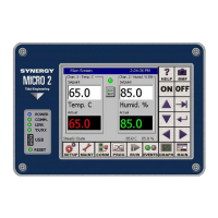
Identifies the principal components of the Synergy Controller Interface Panel, including touch screen and keys.
Describes the Synergy Controller's graphical user interface elements like screen navigation keys and function keys.
Provides access to setup and calibration parameters, organized into 5 folders including Channel, Altitude, and Input.
Explains the Proportional, Integral, and Derivative (PID) algorithm implementation for control channels.
Explains the controller's logging system for capturing and storing data, alarms, and events to the Storage Card.
Details the Chamber Setup Directory used for factory setup, mapping software outputs to chamber hardware.
Details the Panel Lock security feature that restricts access to the Synergy Controller.
Provides information on low storage/memory alarms and alarm actions like relays and screen flashes.
Overview of the program editor for creating multi-channel profiles of Temperature, Humidity, and Altitude.
Details the step-by-step guide (Add Step Wizard) for adding and inserting program steps into a new program.
Explains the five different step types: Setpoint, Jump Loop, Waitfor, Auto Start, and Stop, with detailed descriptions.
Explains how to start, stop, pause, and dynamically edit programs using the Run screen buttons.
Describes how to set steady state setpoints and control chamber power (On/Off) from the Main screen.
Covers options for Main screen configuration, including Process Graph, text size, and sensor displays.
Explains how to configure the logging system using folders for Setup, Options, Profiles, and Data.
Summarizes the six key steps for installing the Synergy Controller, from configuration to system verification.
Guides the user to select the appropriate chamber configuration for installation.
Details the steps for configuring the controller after mounting and wiring, including chamber type and input calibration.
Identifies output mappings for standard chamber definitions built into the controller.
Explains PID algorithms and tuning parameters for channels, including Proportional, Integral, and Derivative.
Details cascade control, a method using two loops for better performance and faster product temperature control.
Describes the calculations for gain (span) and offset for a two-point calibration process.
Explains End-to-End calibration by comparing a reference temperature reading against the controller reading.
Describes commands for remote control, monitoring, and programmatic profile creation, saving, and execution.
Explains the feature for sending alarm, test results, and log file emails automatically to computers and phones.
Details how to set up the chamber and web browser for remote monitoring and control via a web browser.
Defines a macro as a list of Synergy communication commands executed by barcode scan.
Provides instructions for connecting and configuring the ImageTeam 4800 barcode scanner with the Synergy Controller.
| Manufacturer | Tidal Engineering |
|---|---|
| Category | Data Logger |
| Communication Interface | USB |
| Measurement Channels | 8 differential or 16 single-ended |
| Input Types | ±10V, ±2.5V, ±640mV, ±160mV, 0-20mA, Digital Input, Frequency, Thermocouple, RTD, Resistance |
| Sampling Rate | Up to 100 Hz |
| Memory | 4MB internal non-volatile flash memory |
| Power Supply | 9-36 VDC |
| Operating Temperature | -40°C to +85°C |
| Humidity Range | 0-95% RH, non-condensing |