18
Symbols on the instrument
Attention! Observe user instructions!
This devices may not be disposed with the domestic
waste
(
WEEE 2012/19/EU).
Please contact service@tietzsch.de in regard to the return
of old devices.
Indicates EC conformity
TR
on
RT
o
On-time at highest nominal voltage
Recovery time after tests with highest nominal voltage
Device for live working
Push-button (switched)
2
3
4
5
1
6
7
8
9
10
12
14
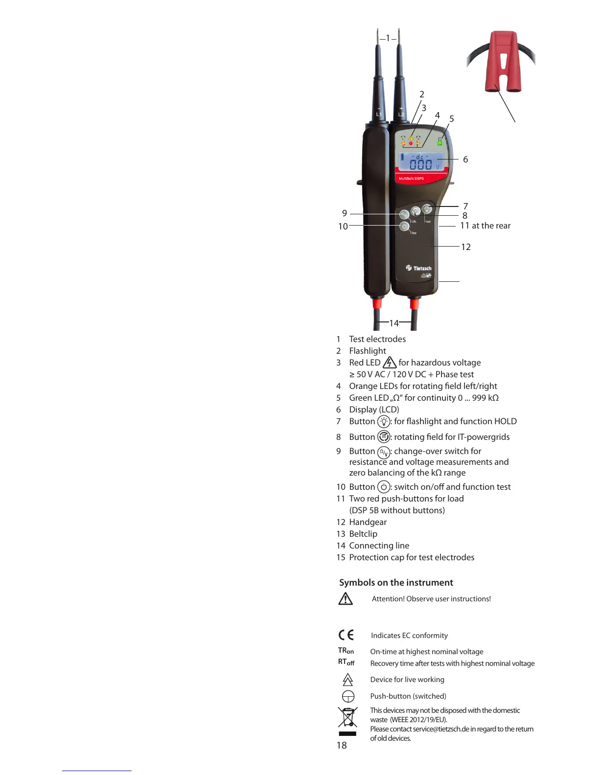
1 Test electrodes
2 Flashlight
3 Red LED for hazardous voltage
≥ 50 V AC / 120 V DC + Phase test
4 Orange LEDs for rotating eld left/right
5 Green LED „Ω“ for continuity 0 ... 999 kΩ
6 Display (LCD)
7 Button
: for ashlight and function HOLD
8 Button
IT
: rotating eld for IT-powergrids
9 Button
Ω
/
V
: change-over switch for
resistance and voltage measurements and
zero balancing of the kΩ range
10 Button : switch on/o and function test
11 Two red push-buttons for load
(DSP 5B without buttons)
12 Handgear
13 Beltclip
14 Connecting line
15 Protection cap for test electrodes
11 at the rear
13 at the rear
15
 Loading...