Page 22
Section 7 - Technical Description
Introduction
This section contains a brief technical description of the 9814, starting with the main-
frame and associated modules, followed by the plug-in boards.
The technical description is divided into the following parts:
1. The Mainframe
2. The Front Panel Electronics Board
3. The Power Module
4. The IEEE Interface Board
5. Microprocessor Board
6. Reference Board
7. Digital to Analogue Board and Module
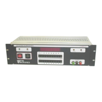
Mainframe
A 19” Eurocard frame houses all boards and modules which plug into a 64 way bus via
DIN 41612 type connectors.
The Front Panel Electronics Board
The microprocessor reads the keypad and drives the display through a 74C923 keypad
encoder and an ICN 7218 8 digit display driver respectively. Two 8 bit latches on the
data bus drive the L.E.D’s above the switches.
Address decoding for these I.C’s is performed by a 74LS138 and a 7400 also on the
P.C.B.
Power Module
The power module contains a 100VA rated mains transformer, DC regulated supplies
and select circuitry for the LOCAL/REMOTE switch and indicators.
The mains transformer has two 120V RMS primary windings and 9V, 11V and two 22V
RMS secondary windings.
The 9V winding connects, via a 2A fuse, to a full wave bridge rectifier and smoothing
capacitor. It supplies a regulated 5V DC at 1A for the microprocessor board, the IEEE
board and front panel display.
The 11V supply is full wave rectified to supply an unregulated 14V DC at 1A. An unregu-
lated 5V DC supply derived from this 14V DC drives the circuit relays and can be pulled
up to 14V on command for latching the relays.
The 18V supply is rectified and regulated at +/- 18V DC for the analogue circuitry.
 Loading...