7
4. Installation
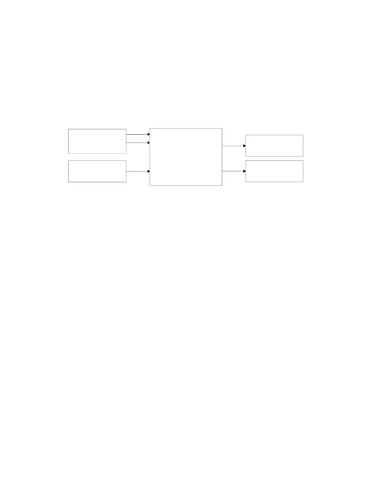
To install a DSP-59+ in a station, the operator must provide power to the DSP-59+ and make
audio input and output connections to the DSP-59+. A typical DSP-59+ installation is shown
below in Figure 3.1.
Receiver/Transceiver
Speaker Output
Station Power Supply
13.8 Vdc
12-16 Vdc
Audio
Input
DSP-59+
Speaker
Speaker
Output
Multimode
Line
Output
Controller
PTT InputPTT Output
Figure 3.1
Power Supply
The DSP-59+ requires a power source of 12 to 16 Volts dc. at 1.0 Amperes.
The center pin of
the power connector is POSITIVE (+), the DSP-59+ chassis is negative. The correct power
plug size is 5.5 mm o.d. and 2.1 mm i.d.
Acceptable power sources include:
• 13.8 volt dc. transceiver power supply (recommended power source for the DSP-59+
because it is better regulated than most plug-in wall outlet supplies).
Note that some
transceivers with internal power supplies have accessory power jacks with insufficient
current output to drive the DSP-59+. Do not use these internal supplies!
• Radio Shack 273-1653 12 V.d.c. @ 1 Ampere plug-in wall supply. Use green tip with center +.
(Switching power supplies are generally noisy and
not
recommended, unless they are
specifically designed to drive amateur radio equipment.)
Connecting Cables
Shielded coaxial cables with RCA phono connectors should be used to minimize the possibility
of RF interference to the DSP-59+. Timewave recommends coaxial video cables with metal
adapters to match the connectors on transceivers and speakers.
The center pin on the DSP-59+
audio input connector must not be connected to the transceiver speaker ground. Check
the connections carefully - this is one of the most common problems in DSP-59+
installations!