10
2. VENTILATION - During normal operation gear reducers build up heat and pressure that MUST be vented to protect
the seals and gears. If not installed at Titan, a brass vent plug contained in a small plastic bag, will be put in a
box or larger bag along with fasteners sent loose for use during eld installation. Remove the top most drain plug
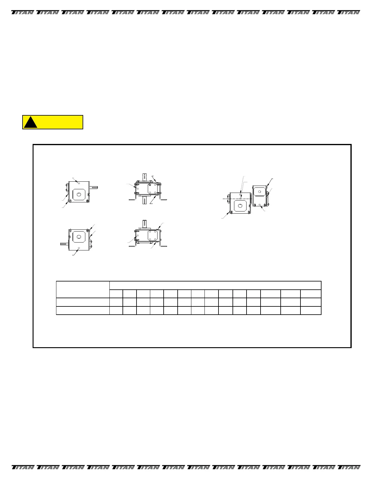
(refer to FIGURE 10) for the position of your reducer) and install the vent plug securely in place.
3. CLEANING - After approximately two to three weeks of operation the reducer MUST be drained, ushed out, and
relled to the proper level with fresh oil. (This is done to remove brass particles caused during the normal wear-in
period of the worm gear.) Afterwards, the oil should be changed in your reducer every 2500 hours or evey
6 months, which ever occurs rst.
WHERE HIGH TEMPERATURES AND/OR DIRTY ATMOSPHERE EXISTS MORE
FREQUENT CHANGES MAY BE NECESSARY. PERIODICALLY CHECK REDUCER
TO ENSURE THAT THE PROPER LEVEL OF OIL IS IN THE REDUCER. TOO
LITTLE OIL WILL CAUSE ACCELERATED WEAR ON THE GEARS. TOO MUCH
OIL CAN CAUSE OVERHEATING, SEAL DETERIORATION, AND LEAKAGE.
4. LUBRICATION - The precision - made gears and bearings in our reducers require high-grade lubricants of the
proper viscosity to maintain trouble- free performance. All standard reducers ordered from the factory are lled
with ISO viscosity grade Mobil Glygoyle 460 polyalkalene glycol (PAG ) lubricant. If oil needs to be added
or changed, ONLY compatible polyglycol lubricants should be used. Contact the factory for more information.
5. TEMPERATURE - Most Titan Units are supplied with wormgear reducers. These units may run at temperatures
between 100 degrees to 200 degrees F. (Higher temperatures are especially common during start up). There is NO
NEED TO WORRY unless temperatures exceed 200 degrees F.
6. GENERAL MAINTENANCE - Regular inspection to insure the reducer bolts and screws are tight, correct alignment
of shaft and/or coupling, no major oil leaks, no excessive heating and no unusual vibration or noise will
insure maximum life and performance of the reducer.
Mounting
Position
UNIT SIZE
813 815 818 821 824 826 830 832 842 852 860 870* 880* 8100*
1 - Worm Over 4 12 12 20 24 40 56 72 112 188 312 35 48 72
2 - Worm Under 8 16 20 28 40 60 84 108 152 304 328 32-3/4 51-1/4 80
Oil Capacities (ounces) - Standard Units
16 0z. = 1 pint
2 pints = 1 quart
4 quarts = 1 gallon
1 gallon = 128 oz. = 231 Cu. in.
DRAIN
LEVEL
VENT
WORM OVER
VENT
LEVEL
DRAIN
VERTICAL OUTPUT
VENT
LEVEL
DRAIN
WORM UNDER
VENT
LEVEL
DRAIN
VERTICAL INPUT
LEVEL*
VENT
DRAIN
VENT
LEVEL
DRAIN
DOUBLE REDUCTION WORM-WORM
(All primary units have
their own oil level)
* Size 842-860 (far side plug)
Note: High oil level applies to all size 842 & larger
secondary & tertiary units regardless of primary
unit type.
Standard Gear Reducer Mounting Positions
& Vent Plug, Level and Drain Locations
* Shipped Dry
FIGURE 10
Return to Table of Contents
 Loading...