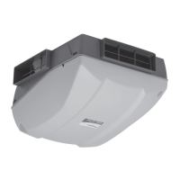
This manual describes the Titon Heat Recovery Ventilation (HRV) units, also known as Mechanical Ventilation with Heat Recovery (MVHR) units, designed for energy-efficient ventilation of dwellings. These units continuously exhaust stale, moist air from bathrooms, toilets, kitchens, and utility rooms, while transferring heat from the extracted air to fresh air supplied to bedrooms and living rooms.
Function Description:
The HRV units provide continuous ventilation, recovering heat from extracted stale air to pre-warm incoming fresh air. This process improves indoor air quality and reduces heating costs. The units are designed to operate continuously, with various features to optimize performance based on environmental conditions and user preferences.
Important Technical Specifications:
- Power Supply: HRV1.3, HRV1.35, HRV1.6, HRV1.65, HRV4, H200 Q Plus units are suitable for 230V ~ 50/60Hz single phase with a fuse rating of 3A. HRV20Q Plus is suitable for 230V ~ 50/60Hz single phase with a fuse rating of 5A.
- Electrical Connection: Supplied with a mains rated 3 core flexible cord (PVC sheathed, brown, blue, and green/yellow 0.75mm²). Must be connected to a local double pole isolation switch with a contact separation of at least 3mm and must be earthed.
- Control/Boost/Communication Cables: Unshielded 4 Core minimum 18-24AWG Stranded, Tinned Copper. Control Cables must not be twisted pairs and should not be placed within 50mm or on the same metal cable tray as 230V~ lighting or power cables. Cable access is via fitted glands suitable for Ø3-6mm cable.
- Ducting: Flexible ducting should only be used for final terminations (max 300mm long, taut, straight). A minimum distance of 200mm between the HRV unit and any sharp bends in ductwork is recommended. Ducting passing through unheated areas or voids should be insulated with at least 25mm of material (thermal conductivity ≤0.04 W/(m.K)) to prevent condensation. Ducts within the heated envelope between external terminals and the unit's ports should be insulated and wrapped with a vapour barrier. Ducting must comply with local Building Regulations where passing through fire barriers or walls. A condensate drain must be fitted to vertical "To Atmosphere" ductwork.
- Condensate Drain: Must incorporate a suitable air-lock trap, be adequately secured, and insulated if passing through unheated voids (below 10°C). It should be installed with a 3 to 5° fall from the unit. Titon recommends a diaphragm-type waste valve (e.g., Hepworth HepvO®) over traditional U-Traps.
- Operating Environment: Not suitable for areas with excessive oil/grease, corrosive/flammable gases/liquids/vapours, ambient temperatures above 40°C or below -5°C, humidity levels above 90%, or wet environments. Not suitable for exterior installation.
- Unit Weights: H200 unit is 32Kg.
Usage Features:
- Fan Speed Settings: Two standard fan speed settings: Continuous Speed and Boost Speed. These are adjustable via rotary potentiometers during commissioning.
- Auto Setback Speed: Reduces ventilation rates automatically, set at the midpoint between minimum Continuous Speed and selected Continuous Speed. Can be enabled by a volt-free one-way switch or combined with Boost Speed using a 3-position switch (TP 508).
- Continuous Speed: Normal continuous extract and supply airflow running speed.
- Boost Speed with Overrun Timer: Increases extract and supply airflow. Configured with stepless independent fan controls and an Overrun Timer (0-60 minutes). Triggered by a volt-free one-way switch (PIR, thermostat, humidistat, standard switch). If left in Boost for over 2 hours (latching switch), the Overrun Timer is disabled, returning the HRV to Continuous Speed when the switch is released.
- auralite® Remote LED Indicator (Optional): A low voltage hard-wired LED indicator panel (fits standard UK patress or recessed backbox) with six LEDs displaying:
- Normal (Solid light): Unit running at Continuous Speed.
- Normal (Flashing light): Unit running at Setback Speed.
- Frost: Unit in Automatic Frost Protection mode.
- Filter: Filters require change.
- Boost (Solid light): Unit running at Boost Speed.
- Boost (Flashing light): Boost Alert is active.
- Summer: Unit in Summer bypass.
- Fault: Unit has a fault (contact installer).
- auralite® Boost Alert: A timer (2 hours) to prevent inadvertent long-term Boost operation. After 2 hours, the Boost LED flashes, and the Overrun Timer is disabled, returning the HRV to Continuous Speed when the switch is released.
- Summer Bypass: Automatically diverts stale air around the heat cell during hot periods, allowing fresh air to enter without preheating.
- SUMMERboost® (Optional): Allows both supply and extract fans to run at full speed when Summer Bypass is activated. Enabled by removing a link wire on the controller PCB. Can be prevented manually (volt-free switch) or automatically (wall-mounted room thermostat) if room temperature falls below the thermostat setting.
- Automatic Frost Protection: Reduces supply ventilation rate during very cold weather to prevent ice buildup in the heat cell, allowing warmer stale air to raise the heat cell temperature.
- Integrated Humidity Sensor: Continuously monitors relative humidity (RH) of extracted air. Triggers Boost Speed when RH rises above a set threshold (variable from 55%RH to 85%RH via stepless independent potentiometer).
- Enthalpy Humidity-Recovery (E suffix units): Recovers some humidity in addition to heat.
Maintenance Features:
- Routine Maintenance: Periodic maintenance (apart from filter changes) must be carried out by a qualified and competent person.
- Cleaning Exterior: Use a clean damp cloth; avoid abrasive cleaners, solvents, or other fluids.
- Cleaning Interior: Isolate power, allow moving parts to stop. Slide out filters. Carefully vacuum dust from the heat exchanger face, unit interior, and bypass. Do not use water or other fluids.
- Front Cover Removal:
- HRV1.3, 1.35, 1.6, 1.65, 4, 4.1 & 4.25: Isolate power, loosen two bottom corner screws, remove center screw, pull cover away from bottom and lift.
- HRV20: Isolate power, loosen two bottom corner screws, remove center screw, remove top cap nuts, pull cover away from bottom and lift.
- H200 Interior Access for Cleaning: Isolate power, remove condensate drain pipe, remove front cover (8 screws), remove black ribbed panel, rotate condensate tray retaining strap, slide condensate tray towards unit center, remove heat cell by pulling strap downwards. Reassembly is the reverse.
- Condensate Tray Replacement: If split, order and fit a replacement part (Part No. XP40042/012 for HRV1, 1.25, 1.3 & 1.35 Q Plus; XP4010649/012 for HRV1.6 & 1.65 Q Plus; XP for HRV4).
- Filter Replacement: Filters should be replaced at least annually or more frequently depending on environmental conditions. The controller will indicate when a change is needed. Replacement filters are available from Titon Direct (www.titondirect.co.uk) and should be replaced with like-for-like components.
- HRV 1.25, 1.3, 1.35, 1.6, 1.65, 4, 4.1 & 4.25: Available in G3, G4 & F7 grades. Remove filter covers/open filter door, slide out old filters (note arrows), slide in new filters (maintain orientation), replace covers.
- HRV20: Available in G4 x 2 and G4 + F7 grades. Open filter cover door (hinged at bottom), slide out old filters, slide in new filters (maintain orientation), close cover.
- H200: Available in G4 panel filters, F7 panel filter & G4 panel filter, or Slim G4 pre-filter. Remove filter covers (4 screws each), slide out old filters, slide in new filters (ensure arrows point towards unit center for cardboard framed pleated filters), replace covers (do not overtighten screws).
- Controller Reset: To reset the controller, power up the unit, rotate Supply and Extract Continuous Speed potentiometers fully anti-clockwise, then rotate Supply and Extract Boost Speed potentiometers fully clockwise. Move the Run/Program Switch from Run to Continuous, then to Boost, then back to Run, waiting two seconds between each movement.
- Hardware Reset: If fan motors are prevented from operating due to repeated supply interruptions, switch off power to the unit for 5 minutes. Restoring power will reset the hardware of both the motor and PCB. Commissioning settings are not affected.