14
V. Alignment and Test Specifications
Adjustments are made on the complete unit during final test basis and upon installation
basis. Installation adjustments are accessible without removing the cover and include a
side tone level adjustment, a microphone gain adjustment, and an audio gain adjustment.
Other adjustments which are not normally adjusted on installation but may require
adjustment different from factory set levels include the squelch level, the dimmer and the
NAV demod level.
A spectrum analyzer is required only for frequency alignment of the Synthesizer module.
If Synthesizer repair is made on a replacement basis, it is not necessary to have a
spectrum analyzer for field service.
Module Alignment
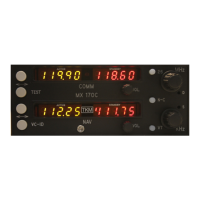
A. Front Panel Assembly (Dwg. SS1930)
The front panel requires no alignment
B. Rear Panel Assembly (Dwgs. SS1945, SS1940)
The rear panel contains three potentiometers which are adjusted as follows:
1. Audio Gain: Apply 3 v rms at 1000 Hz to an aux. audio input and adjust R5 (Audio
Gain) for 5 Watts into a 4 ohm load on the speaker output.
1. Microphone Gain: (R46): Apply .30 Vrms at 1000 Hz to pin 13 of P1. Adjust R46
so
that 12 v p-p is output to the transmitter modulation line.
2. Sidetone Level (R1). Apply .30 vrms at 1000 Hz to pin 13 of P1 and adjust R1 so
that 1.0 vrms appears across a 500 ohm load connected to pin 18 of P1.
C. Computer Board (Dwg. SS1967)
The computer board contains mostly system alignment adjustments which can be set only
with a complete unit. The clock frequency, however, can be set on the board level.
1. Clock Frequency (C5):Adjust C5 so that frequency measured on pin 8 of I2 is
1,000,000 +/- 10 Hz at 70 degrees F room temperature.
D. NAV Receiver (Dwg. SS1867)
1. Apply +15 vdc and –30 vdc to appropriate input leads, local oscillator signal at 3.0 + 2
dbm and a 0 to 14 vdc variable voltage source to Vt.
2. IF Alignment (L2, L3, L4). Apply +7.0 vdc to Vt, 117.90 MHz at –90 dbm to RF in
and 96.50 MHz at +3 dbm to L.O. Adjust L2, L3 and L4 for minimum voltage reading
on Vagc. Apply amplitude modulation of 30% and monitor DMD output. As the
modulation frequency is adjusted from 1.0 to 12.0 Khz the DMD level shall be constant
+/- 1 db. Adjust L2 and L3 as necessary to keep DMD level constant.
3. RF Alignment (T1, T2, L1, T3). With conditions the same as in IF Alignment, but
modulation set to 0, adjust turn spacing on T1, T2, L1, and T3 so that Vagc reading is a
minimum.
4. Change RF to 108.00 MHz and L.O. to 86.60 MHz. Adjust Vt for minimum Vagc.
 Loading...