3
I. INTRODUCTION
This manual contains information on the Michel MX385, manufactured by TKM, Inc.
The information includes operational, mechanical, electrical descriptions, alignment and
test considerations.
A. Purpose of Equipment
The equipment is a 760 channel communication (COMM) transceiver for use in aviation
services and a 200 channel navigation (NAV) receiver to provide VOR/LOC signals to
navigational converters. The NAV receiver also provides frequency selection for remote
mounted Distance Measuring Equipment and Glideslope Receivers.
The MX385 is designed to be used as a direct replacement for the Cessna/ARC RT385A.
The unit is dimensionally identical to the ARC units and can therefore use existing
aircraft installations. Except for improved performance characteristics, the unit is
electrically interchangeable with the ARC unit and will provide the proper audio,
navigation signal and channeling signals for existing installations. New installations can
be made using RT385A installation kits.
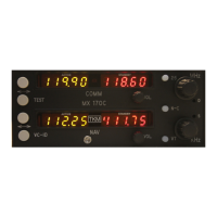
B. Equipment Description
The unit features digital (LED) displays for active (yellow) frequency channel and
standby (red) frequency channel for both COMM and NAV.
For channel selection a MHz knob and a KHz knob are provided. For 25 KHz
increments in COMM, a 25 KHz button is provided. To activate COMM or NAV
frequency selection, an N/C button is provided; a ‘tic’ appears in the selected standby
channel display.
Channel selection operates on the standby channel only. When the desired channel is
indicated in the standby display it may be placed into the active position by depressing
the ‘Flip-Flop’ button located to the left of the displays; the active channel is then placed
into the standby position.
The NAV receiver features a VC/ID button to permit selection of voice or Ident
reception. In the Ident condition a ‘tic’ is displayed on the active NAV channel display.
The COMM transceiver features a test button, which overrides the squelch to verify
proper receiver operation and to allow reception of weak signals. Also provided on the
active COMM display, is a ‘tic’ to indicate transmitter power output.
The master power switch is integrated with the COMM volume control.
 Loading...