Do you have a question about the TLC TAC-07CHSA/XAB1 and is the answer not in the manual?
Instructions for ordering replacement parts, requiring model and part information.
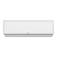
Visual representation and dimensions of the indoor air conditioning unit.
Visual representation and dimensions of the outdoor air conditioning unit.
Diagram illustrating the refrigeration cycle for cooling-only operation.
Diagram illustrating the refrigeration cycle for heat pump operation.
Explanation of remote control buttons and their functions for air conditioning.
Instructions on setting the remote controller type (Cooling Only vs. Heat Pump).
Definitions for abbreviations used in temperature and mode settings.
Details on how the air conditioner operates in automatic mode based on room temperature.
Table detailing initial room and setting temperatures for heat pump modes.
Table detailing initial room and setting temperatures for cooling-only modes.
Explanation of compressor and fan control logic during cooling mode.
Operation details for the dry mode, including temperature and fan speed settings.
Explanation of compressor, fan, and 4-way valve control in heating mode.
Details on the defrosting function, including triggers and operation.
Conditions and procedures for entering and exiting defrost mode.
Conditions for entering and quitting defrost mode based on various factors.
Details on the optional auxiliary electric heating function.
Operation of the fan-only mode, including fan and vane motor control.
Operation and temperature control during sleep mode.
Functionality and settings for the timer feature.
How to use the emergency switch for mode selection and shutdown.
Protections active during emergency operation.
How to activate and deactivate the auto-restart function.
Explanation of various protection functions like compressor, anti-frosting, overheating.
Specifics of anti-frosting protection in cooling mode.
Specifics of overheating protection in heating mode.
How cold air prevention works in heating mode.
Table of failure codes, their causes, and display indicators.
Wiring diagram for the indoor unit.
Wiring diagram for the outdoor unit.
Exploded view and parts list for the indoor unit model TAC-07CHSA/XAB1.
Exploded view and parts list for the outdoor unit model TAC-07CHSA/XAB1.
Exploded view and parts list for the indoor unit model TAC-09CHSA/XAB1.
Exploded view and parts list for the outdoor unit model TAC-09CHSA/XAB1.
Exploded view and parts list for the indoor unit model TAC-12CHSA/XAB1.
Exploded view and parts list for the outdoor unit model TAC-12CHSA/XAB1.
Exploded view and parts list for the indoor unit model TAC-18CHSA/XAB1.
Exploded view and parts list for the outdoor unit model TAC-18CHSA/XAB1.
Exploded view and parts list for the indoor unit model TAC-24CHSA/XAB1.
Exploded view and parts list for the outdoor unit model TAC-24CHSA/XAB1.
Safety guidelines and recommendations for installing the air conditioner unit.
Safety guidelines and recommendations for operating and maintaining the air conditioner.
Identification and naming of key parts within the indoor unit.
Identification and naming of key parts within the outdoor unit.
Details on pipe sizes and maximum lengths for refrigerant connections.
Guidelines for selecting appropriate wire sizes for power cords based on appliance amperage.
Procedures for first-time installation of indoor and outdoor units.
Step-by-step guide for installing the indoor unit mounting plate.
Instructions for drilling wall holes for refrigerant piping and drain.
Steps for making electrical connections to the indoor unit.
Procedures for connecting refrigerant pipes to the unit.
Guidelines for handling and connecting refrigerant pipes to prevent contamination.
Steps for connecting refrigerant pipes to the indoor unit.
Instructions for proper installation of the condensate drain hose.
Guidelines for piping, cable, and drain hose installation on the right side.
Steps for making electrical connections to the outdoor unit.
Procedures for screwing flare nuts to outdoor unit couplings.
Process of removing air and humidity from the refrigerant circuit using a vacuum pump.
Troubleshooting steps for when the air conditioner unit fails to power on.
Troubleshooting guide for when the indoor fan fails to operate.
Troubleshooting steps for compressor or outdoor fan non-operation.
Troubleshooting steps for when the air conditioner vanes fail to move.
Troubleshooting for issues with switching between cooling and heating modes.
Reasons and solutions for display errors E1 and E2.
Reasons and solutions for display error E6.
Diagnosis and solution for indoor motor failure.
Diagnosis and solution for indoor main PCB failure.
Table of thermistor resistance and voltage values at different temperatures.
| Brand | TLC |
|---|---|
| Model | TAC-07CHSA/XAB1 |
| Category | Air Conditioner |
| Language | English |