Injection Molding Machine Chapter 4
V3.0
4-6
A
10
V1 0/ 0
:
The output value of the first set proportional flow valve. On
the left side is the command number
,
on the right side is
the command value.
A
11
P1 0/ 0
:
The output value of the first set proportional pressure valve.
On the left side is the command number
,
on the right side is
the command value.
A
12
V2 0/ 0
:
The output value of the second set proportional flow valve.
On the left side is the command number
,
on the right side is
the command value.
A
13
P2 0/ 0
:
The output value of the second set proportional pressure
valve. On the left side is the command number
,
on the right
side is the command value.
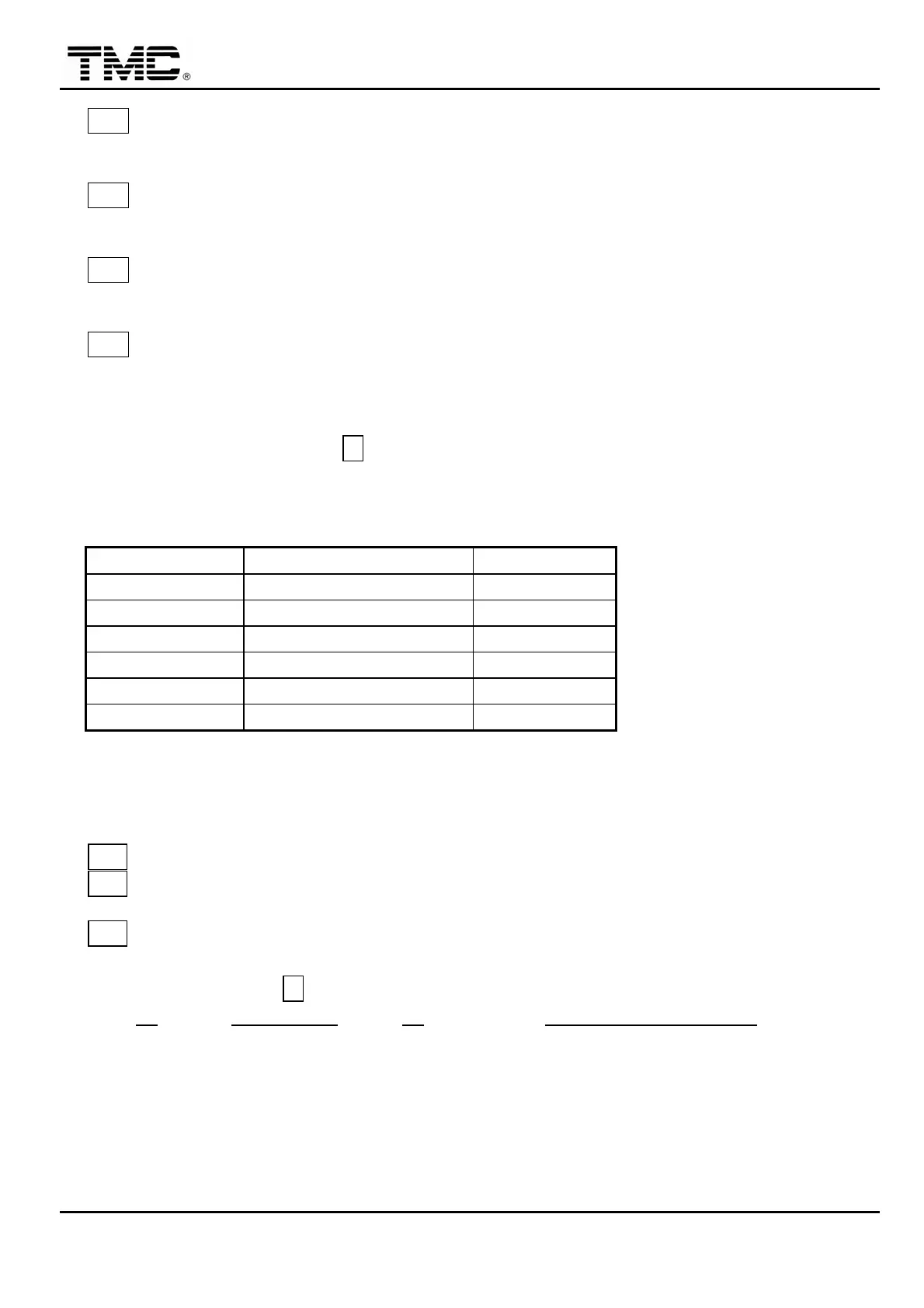
2.0.2 Parameters setting area
B
Operator screen is with GREEN background
,
while engineering screen is with BLUE
background.
ITEM FORWORDGROUND BACKGROUND
SPEED BLACK BLUE
POSITION RED GREY
PRESSURE RED LIGHT BLUE
TIME BLACK
FUNCTION DARK BLUE
ACTUAL VALUE WHITE (READ ONLY)
Use
※
key to enter decimal point.
2.0.3 Help text area
C1
Instruction of the position of cursor & massage of alarm.
C2
Display the minimum and maximum limit value at present cursor
position that can be entered.
C3
The display of typing
,
check ok than push ENTER
2.0.4 Function key area
D
Push F1 to enter MAIN MENU
,
push F1 twice to enter MACHINE MONITORING.
 Loading...